DMP 128 • Setup Guide (Continued)
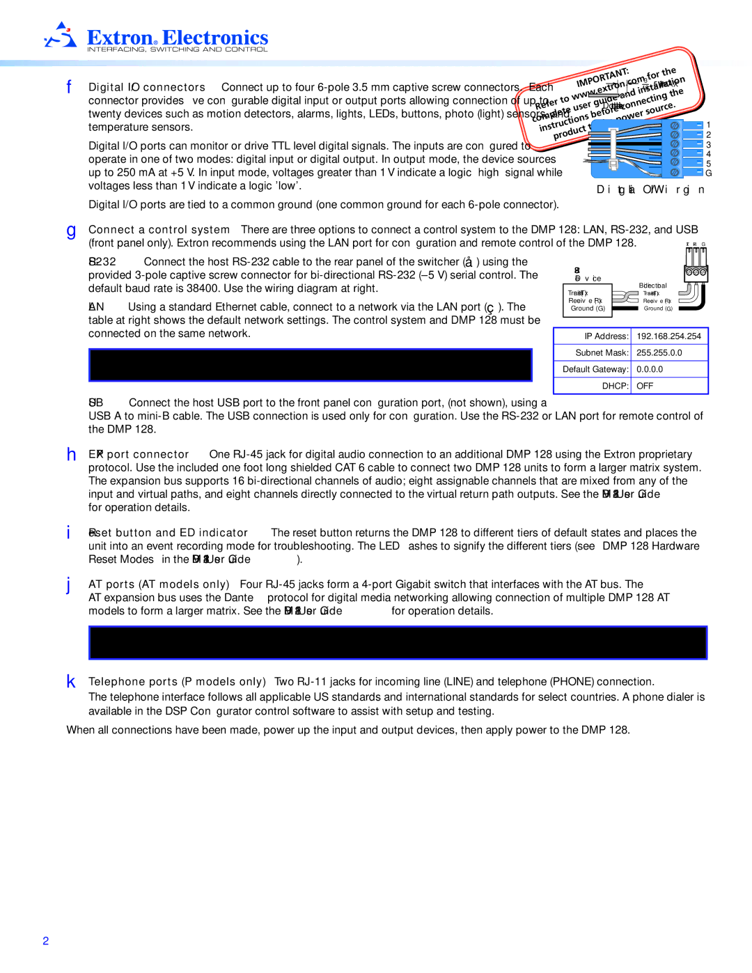
F Digital I/O connectors — Connect up to four
Digital I/O ports can monitor or drive TTL level digital signals. The inputs are configured to operate in one of two modes: digital input or digital output. In output mode, the device sources up to 250 mA at +5 V. In input mode, voltages greater than 1 V indicate a logic ‘high’ signal while voltages less than 1 V indicate a logic 'low'.
Digital I/O ports are tied to a common ground (one common ground for each
![]()
![]()
![]() 163 " (5 mm) MAX.
163 " (5 mm) MAX.
Do not tin the wires!
![]() 1
1
![]() 2
2
![]() 3
3
![]() 4
4
![]() 5
5
![]() G
G
Digital I/O Wiring
G Connect a control system — There are three options to connect a control system to the DMP 128: LAN, RS‑232, and USB (front panel only). Extron recommends using the LAN port for configuration and remote control of the DMP 128.
LAN — Using a standard Ethernet cable, connect to a network via the LAN port (Ç). The table at right shows the default network settings. The control system and DMP 128 must be connected on the same network.
NOTE: To connect the DMP 128 directly to a computer Ethernet port, use a crossover Ethernet cable.
Device
|
| Bidirectional |
Transmit (Tx) |
| |
| Transmit (Tx) | |
Receive (Rx) |
| Receive (Rx) |
Ground ( G ) |
| Ground ( G ) |
| ||
| ||
|
|
|
IP Address: | 192.168.254.254 |
|
|
Subnet Mask: | 255.255.0.0 |
|
|
Default Gateway: | 0.0.0.0 |
|
|
DHCP: | OFF |
|
|
USB — Connect the host USB port to the front panel configuration port, (not shown), using a
USB A to
H EXP port connector — One
I Reset button and LED indicator — The reset button returns the DMP 128 to different tiers of default states and places the unit into an event recording mode for troubleshooting. The LED flashes to signify the different tiers (see “DMP 128 Hardware Reset Modes” in the DMP 128 User Guide).
J AT ports (AT models only) — Four
AT expansion bus uses the Dante™ protocol for digital media networking allowing connection of multiple DMP 128 AT models to form a larger matrix. See the DMP 128 User Guide for operation details.
NOTE: The Dante Controller software is required for configuration of the AT expansion bus (see Dante Controller Software Installation (AT models only) on the next page).
K Telephone ports (P models only) — Two
The telephone interface follows all applicable US standards and international standards for select countries. A phone dialer is available in the DSP Configurator control software to assist with setup and testing.
When all connections have been made, power up the input and output devices, then apply power to the DMP 128.
2