Manuals
/
Extron electronic
/
TV and Video
/
TV Converter Box
Extron electronic
setup guide
DSC 3G-HD A Scaler Setup Guide, Installation, Rack Mounting
Models:
DSC 3G-HD A
1
1
4
4
Download
4 pages
2.66 Kb
1
2
3
4
Install
Configuring the DSC 3G-HD A
Output Rate Reset
Basic SIS Commands
Page 1
Image 1
Page 1
Page 2
Page 1
Image 1
Page 1
Page 2
Contents
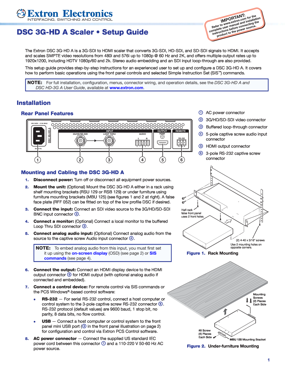
Installation
DSC 3G-HD A Scaler Setup Guide
Rear Panel Features
Mounting and Cabling the DSC 3G-HD A
Configuring the DSC 3G-HD A
DSC 3G-HD A Setup Guide Continued
Front Panel Overview
Locking the Front Panel Executive Mode
Setting Up the DSC 3G-HD A Using the OSD Menu
Output Rate Reset
Output Scaler Rates
ASCII Command
Command
Response
Additional Description
Top
Page
Image
Contents