DVI 104 Tx/Rx, cont’d
Rear panel features
|
|
|
|
|
| 1 | 3 | 6 |
| 8 |
|
|
|
|
| 3 |
|
|
|
|
|
|
| Male Connector |
| ||
|
|
|
|
|
|
|
|
|
| ||||
|
| 9 |
|
|
| 17 19 | 22 | 24 |
|
|
| ||
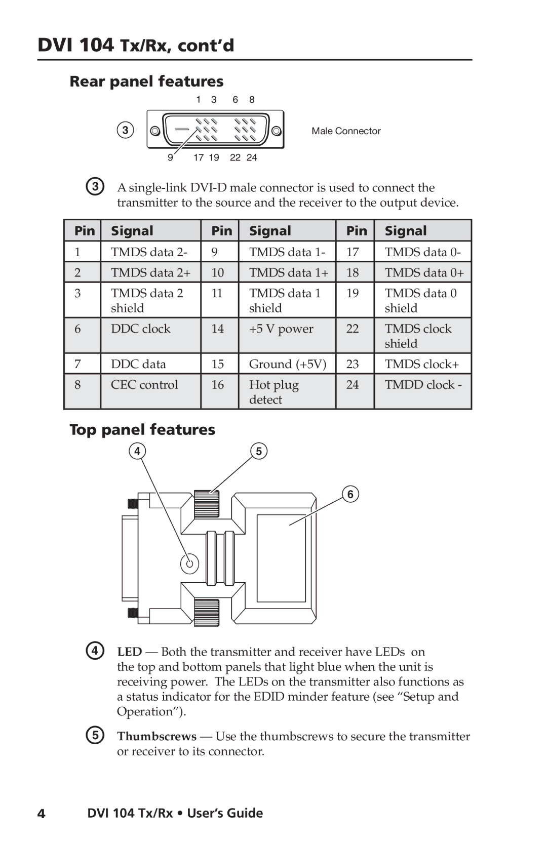
C | A | ||||||||||||
|
| transmitter to the source and the receiver to the output device. | |||||||||||
|
|
|
|
|
|
|
|
|
| ||||
Pin |
| Signal |
| Pin |
| Signal | Pin |
| Signal | ||||
|
|
|
|
|
|
|
|
|
|
| |||
1 |
| TMDS data 2- |
| 9 |
|
| TMDS data 1- | 17 |
| TMDS data 0- | |||
2 |
| TMDS data 2+ |
| 10 |
|
| TMDS data 1+ | 18 |
| TMDS data 0+ | |||
|
|
|
|
|
|
|
|
|
|
| |||
3 |
| TMDS data 2 |
| 11 |
|
| TMDS data 1 | 19 |
| TMDS data 0 | |||
|
| shield |
|
|
|
| shield |
|
| shield | |||
6 |
| DDC clock |
| 14 |
|
| +5 V power | 22 |
| TMDS clock | |||
|
|
|
|
|
|
|
|
|
|
|
|
| shield |
7 |
| DDC data |
| 15 |
|
| Ground (+5V) | 23 |
| TMDS clock+ | |||
8 |
| CEC control |
| 16 |
|
| Hot plug | 24 |
| TMDD clock - | |||
|
|
|
|
|
|
|
|
|
| detect |
|
|
|
Top panel features
45
6
D | LED — Both the transmitter and receiver have LEDs on |
| the top and bottom panels that light blue when the unit is |
| receiving power. The LEDs on the transmitter also functions as |
| a status indicator for the EDID minder feature (see “Setup and |
| Operation”). |
E | Thumbscrews — Use the thumbscrews to secure the transmitter |
| or receiver to its connector. |
4DVI 104 Tx/Rx • User’s Guide
