DVI DL 201 TX/RX, DVI DL 201 Rx specifications
Extron Electronics is renowned for its high-quality audio-visual solutions, and their DVI DL 201 TX/RX and DVI DL 201 RX are no exception. These devices are designed to facilitate digital video signal transmission over long distances, making them ideal for professional AV setups in educational institutions, corporate environments, and large venues.The Extron DVI DL 201 TX (transmitter) and DVI DL 201 RX (receiver) feature advanced technology that supports DVI Dual Link video signals. This capability allows for the transmission of high-resolution video up to 2560x1600 at 60Hz, ensuring crisp and clear visuals essential for modern presentations and video playback.
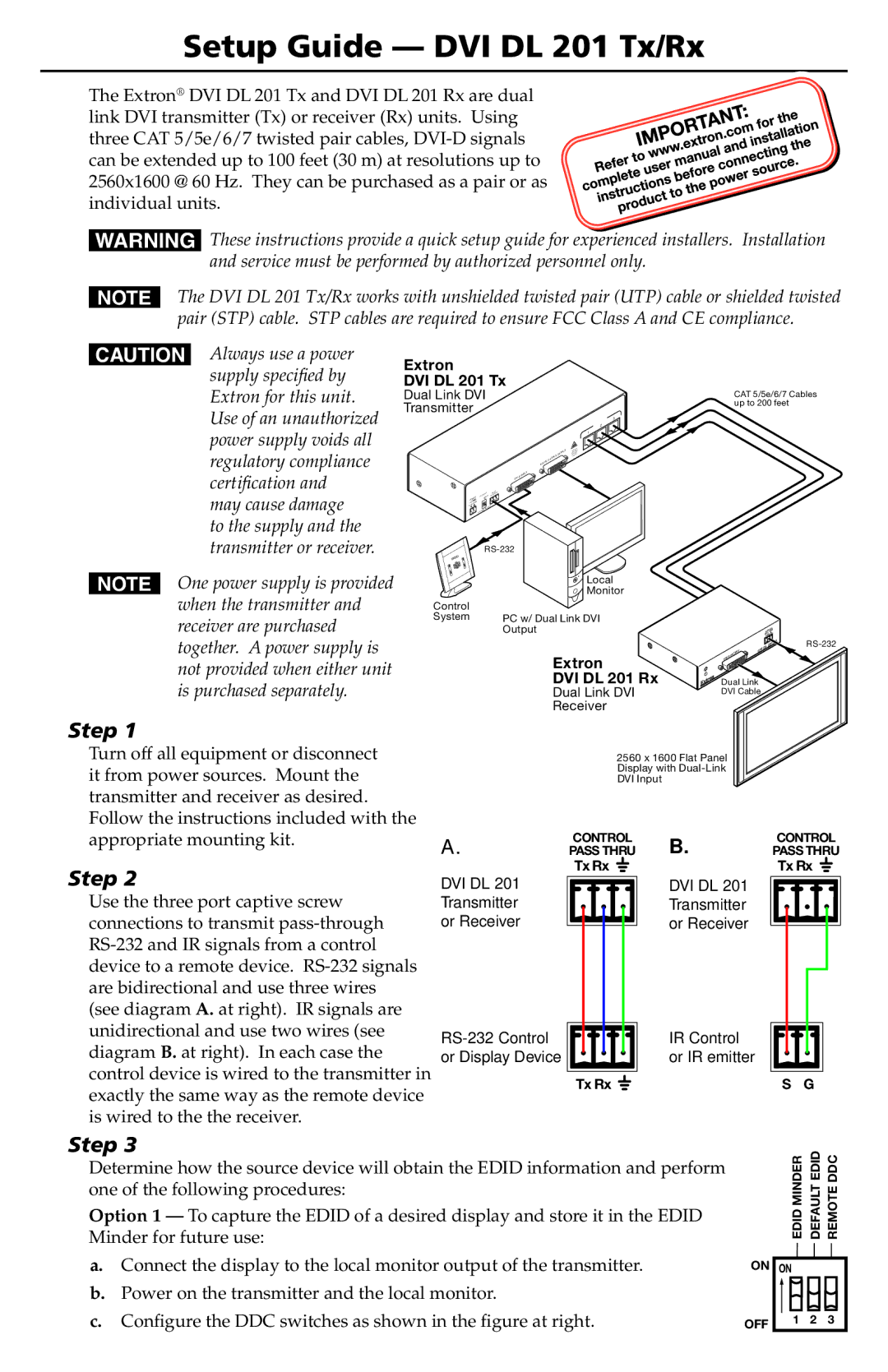
One of the standout features of the DVI DL 201 series is its ability to extend DVI signals up to 200 feet (60 meters) using a single CAT 6 cable. This long-distance capability is particularly beneficial in expansive installations where traditional cabling may not suffice. The use of Exton’s advanced technology allows these devices to maintain signal integrity even at longer distances, mitigating concerns about video degradation.
The DVI DL 201 TX/RX is equipped with hot-plug detection, ensuring that both the transmitter and receiver can automatically recognize connected devices without the need for manual intervention. This enhances ease of use and simplifies the setup process for system integrators. Additionally, the devices are designed with a compact form factor, allowing for flexibility in installation without taking up excessive space.
Another notable characteristic of the DVI DL 201 series is its compatibility with a range of DVI sources and displays, making it a versatile solution in mixed technology environments. This flexibility, combined with their durability, makes these devices a reliable choice for any AV installation.
Furthermore, Extron incorporates thorough engineering in their products, ensuring that both the DVI DL 201 TX and RX meet high standards of performance and reliability. The devices are backed by Extron’s comprehensive support and warranty services, providing peace of mind for end-users.
In conclusion, the Extron DVI DL 201 TX/RX and DVI DL 201 RX introduce a robust solution for extending DVI signals, ensuring high-quality video transmission across considerable distances. With their advanced features and technologies, they are an excellent choice for any professional AV application.