MLC 104 Plus Series specifications
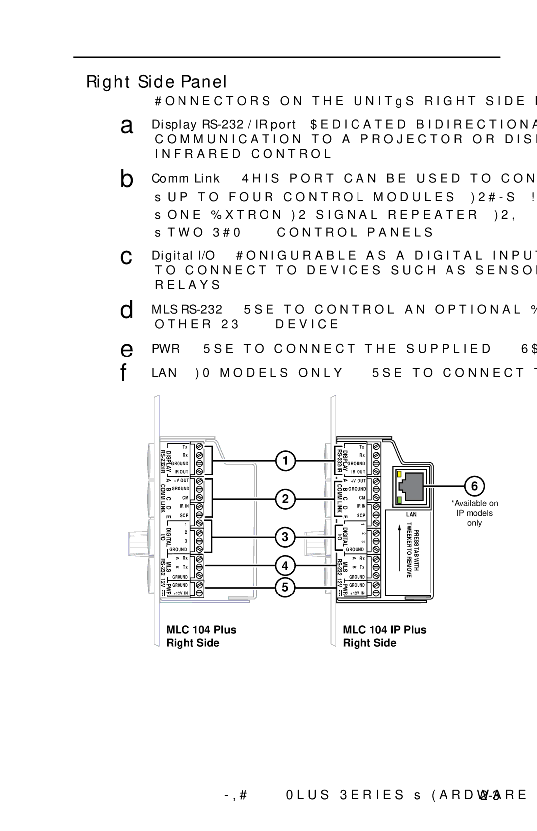
The Extron Electronics MLC 104 Plus Series is an advanced control system designed for modern AV environments, providing users with intuitive and efficient management of multimedia devices. This series is particularly well-suited for classrooms, conference rooms, and other collaborative spaces, where ease of use and reliability are paramount.One of the standout features of the MLC 104 Plus is its customizable control interface. The unit is equipped with multiple buttons, which can be programmed to operate various AV devices such as projectors, displays, and video conferencing equipment. This flexibility allows users to create tailored controls based on their specific needs, promoting a user-friendly experience.
The MLC 104 Plus incorporates Extron's proprietary technologies such as Global Configurator Plus software, which streamlines the installation and configuration process. This software simplifies programming, enabling integrators to create a customized user interface quickly. Additionally, the device supports numerous AV control protocols, ensuring compatibility with a wide range of third-party equipment.
Another significant characteristic of the MLC 104 Plus is its powerful built-in functionality. This includes support for AV data communication through Ethernet, enabling the device to operate and monitor AV systems remotely. Users can manage their systems from different locations, thus enhancing operational efficiency.
The MLC 104 Plus also features a user-friendly graphical display that provides clear feedback during operation. This built-in LCD screen shows status information and control options, ensuring users can easily access necessary controls without confusion. Its compact design allows for easy integration into any environment, whether mounted on a wall or placed on a table.
The series also emphasizes reliability through its robust construction and high-quality components, ensuring long-lasting performance in demanding environments. The MLC 104 Plus Series is designed to support secure and robust connections, reducing the potential for signal interference and enhancing the overall user experience.
In summary, the Extron MLC 104 Plus Series is a versatile, intuitive, and powerful solution for AV control, equipped with a customizable interface, extensive compatibility, and efficient setup capabilities. Its combination of advanced technology and user-friendly features makes it an ideal choice for any modern AV installation, setting a new standard in multimedia management.

