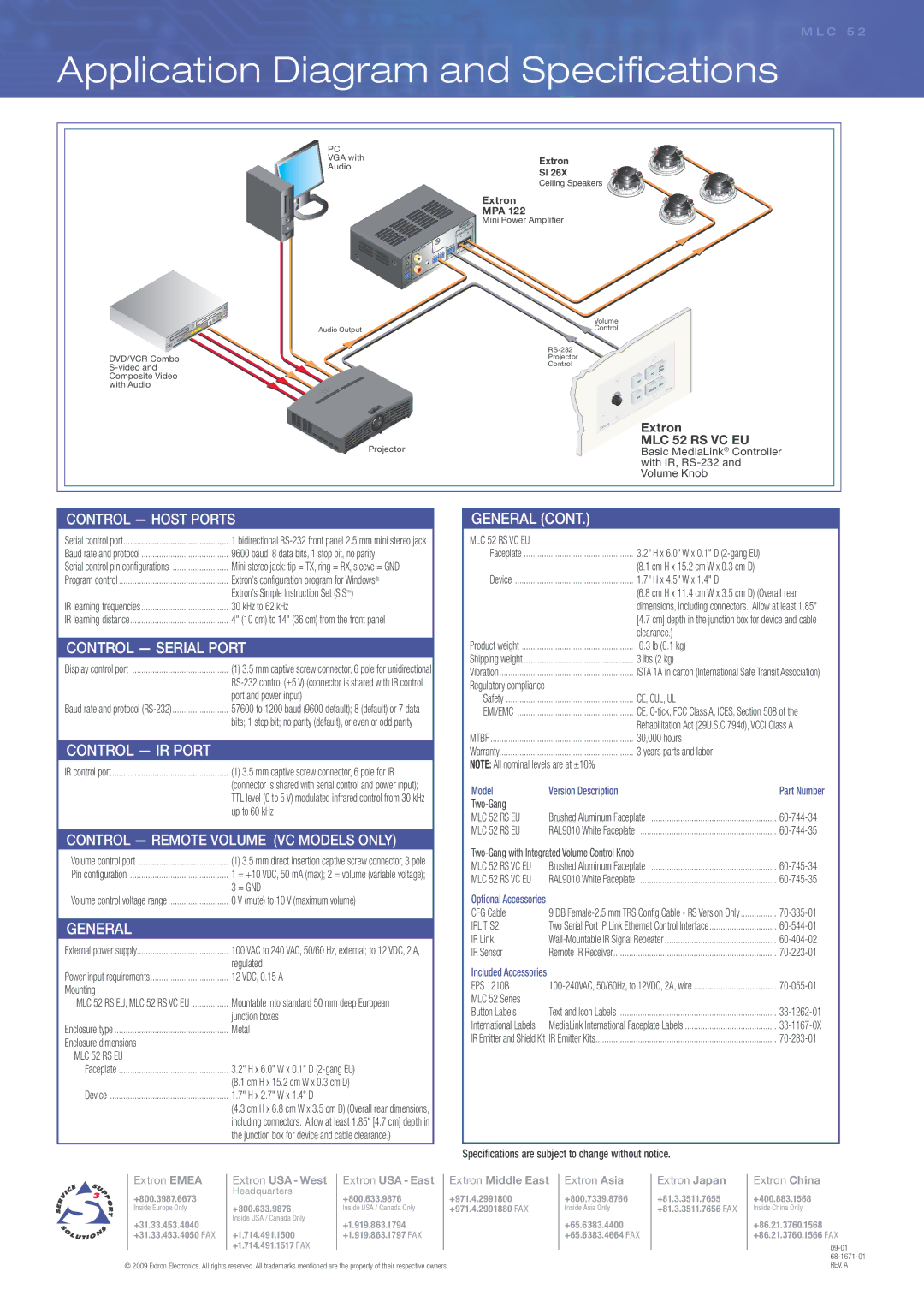
Extron electronic MLC 52 RS VC EU, MLC 52 RS EU manual Application Diagram and Specifi cations

Models: MLC 52 RS VC EU MLC 52 RS EU

1 4
Download 4 pages 52.9 Kb
Page 4
Image 4

specifications

M L C 5 2


Application Diagram and Specifi cations

PC


VGA with

Extron

Audio

SI 26X


Ceiling Speakers


Extron


MPA 122


122

Mini Power Ampli￿er


MPA


OUTPUTSKERS


SPEAR


4/8

Ohms


L


INPUTS


REMOTE


R

VOL/MUT

E


10V


L

L


R


POWE


R


.


12VMAX


3A


Volume


Audio Output


Control


RS-232

DVD/VCR Combo


Projector

S-video and


Control

Composite Video with Audio

Projector


DOC


CAM


PC


OFF

DVD


52

VIDEO

ML

C


ON


Extron

MLC 52 RS VC EU

Basic MediaLink® Controller with IR, RS-232 and Volume Knob

CONTROL — HOST PORTS

Serial control port

1 bidirectional RS-232 front panel 2.5 mm mini stereo jack

Baud rate and protocol

9600 baud, 8 data bits, 1 stop bit, no parity

Serial control pin confi gurations

Mini stereo jack: tip = TX, ring = RX, sleeve = GND

Program control

Extron’s confi guration program for Windows®


Extron’s Simple Instruction Set (SIS)

IR learning frequencies

30 kHz to 62 kHz

IR learning distance

4" (10 cm) to 14" (36 cm) from the front panel

CONTROL — SERIAL PORT

Display control port

(1) 3.5 mm captive screw connector, 6 pole for unidirectional


RS-232 control (±5 V) (connector is shared with IR control


port and power input)

Baud rate and protocol (RS-232)

57600 to 1200 baud (9600 default); 8 (default) or 7 data


bits; 1 stop bit; no parity (default), or even or odd parity

CONTROL — IR PORT

IR control port

(1) 3.5 mm captive screw connector, 6 pole for IR


(connector is shared with serial control and power input);


TTL level (0 to 5 V) modulated infrared control from 30 kHz


up to 60 kHz

CONTROL — REMOTE VOLUME (VC MODELS ONLY)

Volume control port

(1) 3.5 mm direct insertion captive screw connector, 3 pole

Pin confi guration

1

= +10 VDC, 50 mA (max); 2 = volume (variable voltage);


3

= GND

Volume control voltage range

0 V (mute) to 10 V (maximum volume)

GENERAL

External power supply

100 VAC to 240 VAC, 50/60 Hz, external; to 12 VDC, 2 A,


regulated

Power input requirements

12 VDC, 0.15 A

Mounting


MLC 52 RS EU, MLC 52 RS VC EU

Mountable into standard 50 mm deep European


junction boxes

Enclosure type

Metal

Enclosure dimensions


MLC 52 RS EU


Faceplate

3.2" H x 6.0" W x 0.1" D (2-gang EU)


(8.1 cm H x 15.2 cm W x 0.3 cm D)

Device

1.7" H x 2.7" W x 1.4" D


(4.3 cm H x 6.8 cm W x 3.5 cm D) (Overall rear dimensions,


including connectors. Allow at least 1.85" [4.7 cm] depth in


the junction box for device and cable clearance.)

GENERAL (CONT.)

MLC 52 RS VC EU


Faceplate

3.2" H x 6.0" W x 0.1" D (2-gang EU)


(8.1 cm H x 15.2 cm W x 0.3 cm D)

Device

1.7" H x 4.5" W x 1.4" D


(6.8 cm H x 11.4 cm W x 3.5 cm D) (Overall rear


dimensions, including connectors. Allow at least 1.85"


[4.7 cm] depth in the junction box for device and cable


clearance.)

Product weight

0.3 lb (0.1 kg)

Shipping weight

3 lbs (2 kg)

Vibration

ISTA 1A in carton (International Safe Transit Association)

Regulatory compliance


Safety

CE, CUL, UL

EMI/EMC

CE, C-tick, FCC Class A, ICES, Section 508 of the


Rehabilitation Act (29U.S.C.794d), VCCI Class A

MTBF

30,000 hours

Warranty

3 years parts and labor

NOTE: All nominal levels are at ±10%


Model

Version Description

Part Number

Two-Gang


MLC 52 RS EU

Brushed Aluminum Faceplate

60-744-34

MLC 52 RS EU

RAL9010 White Faceplate

60-744-35

Two-Gang with Integrated Volume Control Knob


MLC 52 RS VC EU

Brushed Aluminum Faceplate

60-745-34

MLC 52 RS VC EU

RAL9010 White Faceplate

60-745-35

Optional Accessories


CFG Cable

9 DB Female-2.5 mm TRS Confi g Cable - RS Version Only

70-335-01

IPL T S2

Two Serial Port IP Link Ethernet Control Interface

60-544-01

IR Link

Wall-Mountable IR Signal Repeater

60-404-02

IR Sensor

Remote IR Receiver

70-223-01

Included Accessories


EPS 1210B

100-240VAC, 50/60Hz, to 12VDC, 2A, wire

70-055-01

MLC 52 Series


Button Labels

Text and Icon Labels

33-1262-01

International Labels

MediaLink International Faceplate Labels

33-1167-0X

IR Emitter and Shield Kit

IR Emitter Kits

70-283-01

Specifications are subject to change without notice.

Extron EMEA

Extron USA - West

Extron USA - East

Extron Middle East

+800.3987.6673

Headquarters

+800.633.9876

+971.4.2991800


Inside Europe Only

+800.633.9876

Inside USA / Canada Only

+971.4.2991880 FAX

+31.33.453.4040

Inside USA / Canada Only

+1.919.863.1794


+31.33.453.4050 FAX

+1.714.491.1500

+1.919.863.1797 FAX


+1.714.491.1517 FAX


© 2009 Extron Electronics. All rights reserved. All trademarks mentioned are the property of their respective owners.

Extron Asia

+800.7339.8766

Inside Asia Only

+65.6383.4400 +65.6383.4664 FAX

Extron Japan

+81.3.3511.7655 +81.3.3511.7656 FAX

Extron China

+400.883.1568

Inside China Only

+86.21.3760.1568 +86.21.3760.1566 FAX

09-01

68-1671-01 REV. A

Page 4
Image 4
Extron electronic MLC 52 RS VC EU, MLC 52 RS EU manual Application Diagram and Specifi cations, Model Version Description