Manuals
/
Extron electronic
/
Home Audio
/
Stereo Amplifier
Extron electronic
MPA 401
manual
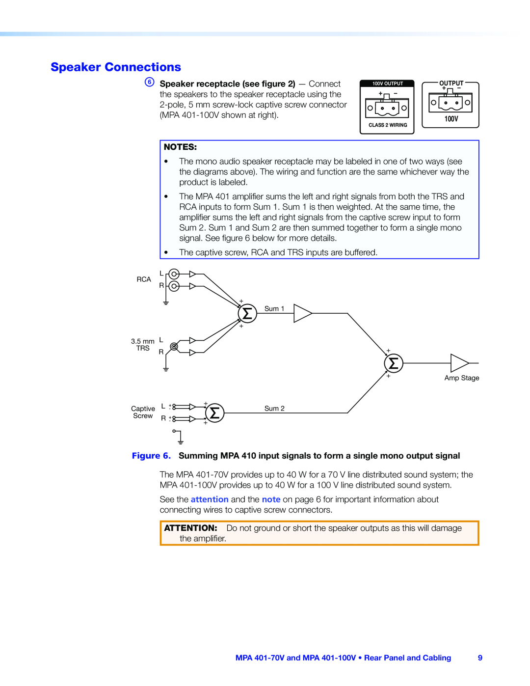
Speaker Connections
Models:
MPA 401
1
15
22
22
Download
22 pages
10.3 Kb
12
13
14
15
16
17
18
19
Troubleshooting
Specification
Warranty
Rack Mounting Procedure
Setting Input Level
Wiring for remote control
Plenum Placement
Safety
Mini Power Amplifiers
Page 15
Image 15
Page 14
Page 16
Page 15
Image 15
Page 14
Page 16
Contents
Audio
MPA 401 Series
Mini Power Amplifiers
User Guide
Instructions de sécurité Français
Safety Instructions
Safety Instructions English
Chinese Simplified(简体中文)
FCC Class B Notice
Specifications Availability
Conventions Used in this Guide
Notifications
Rear Panel and Cabling
Contents
Setup and Operation
Introduction
MPA 401-70Vand MPA 401-100V Contents
Introduction
Important Safety Instructions
Important Safety Instructions
MPA 401-70Vand MPA 401-100VFeatures
Figure 1. Typical Application for the MPA
MPA 401-70Vand MPA 401-100VDescription
MPA 401-70Vand MPA 401-100V Introduction
MPA 401-70Vand MPA 401-100VFeatures
Rear Panel
Rear Panel Power Input Audio Inputs
Remote Input Connector Speaker Connections
Rear Panel and Cabling
Power Input
Audio Inputs
Remote Input Port
Wiring for remote control
Page
Speaker Connections
Setting Bass and Treble Remote Control Options
Setup and Operation
Front Panel Features
Front Panel Features Setting Input Level
Setting Bass and Treble
Setting Input Level
Extron SI 3CT LP
Remote Control Options
MPA 401-70Vand MPA 401-100V Setup and Operation
Extron MPA
Troubleshooting
Amplifier Fails to Exit Standby Mode Promptly
Amplifier Enters Standby Mode Too Early
Mounting
Plenum Placement
Tabletop Placement
Reference Material
Under-desk, Through-desk,and Projector Mounting
Rack Mounting Procedure
Extron Warranty
Top
Page
Image
Contents