MPS 602 Series • Setup Guide
|
|
|
|
| ANT: | complete | ||||
|
|
|
| T |
| the | ||||
| IMPOR.com | for |
| and | ||||||
| instructions, |
| ||||||||
| .extr |
|
|
|
| |||||
to |
| on |
|
|
|
| the | |||
,installationoreconnectingce |
| |||||||||
| www |
|
|
|
|
|
|
| . |
|
Go guide |
| bef |
|
| wersour |
| ||||
user |
|
|
| the | po |
|
|
| ||
specifications |
|
|
|
|
|
|
| |||
| product | to |
|
|
|
|
|
|
| |
|
|
|
|
|
|
|
|
| ||
This guide provides basic instructions for an experienced technician to install, set up, and operate the Extron Media Presentation Switcher, MPS 602. Installation and service must be performed by authorized personnel only. For additional information and specifications, see the MPS 602 product page at www.extron.com.
Step 1 — Disconnect Power and Mount the MPS 602
Disconnect power to the MPS 602 and turn off all devices that will be connected to it. The MPS 602 is housed in a full rack width,
8.5inch deep, 1U high metal enclosure that can sit on a table with the provided rubber feet or can be rack mounted. Select a suitable mounting location, choose an appropriate mounting option, and follow the instructions provided with the mounting kit.
Step 2 — Cable the Switcher
a b
![]()
| 1 |
INPUTS | 2 |
50/60 Hz
d
4
RGB OUT
3
5
c
f g | k | n q |
|
| IR |
|
|
| L | 1 | R | L | 2 | R | L | 3 R |
| AUDIOOUT | L VARIABLE R |
|
| MPS 602 SA | ||
|
|
|
|
|
| AUDIOIN | MUTEHDMI AUDIO PHANTOMPOWER |
|
|
| |||||||||||
|
| IR |
| OUTPUTS | L | 4 | R | L | 5 | R | MIC LINE | L FIXED | R |
| R | ||||||
| 6 | Tx Rx G Tx Rx |
| SELECT |
|
|
|
|
|
|
|
|
|
|
|
| AMP OUT | REMOTE |
| ||
|
| OVER DTP |
| HDMI |
|
|
|
|
|
|
|
|
|
|
|
| 8Ω / 4Ω |
|
| ||
SIG | LINK | OVER DTP | SIG | LINK |
|
|
|
|
|
|
|
|
|
|
|
| L | R |
|
| |
|
|
|
|
|
|
|
|
|
|
|
|
|
|
|
|
|
| ||||
|
|
|
|
|
|
|
|
|
|
|
|
|
|
|
| MIC |
|
|
|
|
|
DTP IN | Tx Rx G Tx Rx | DTP OUT |
|
|
|
|
|
|
|
|
|
| MIX |
| CLASS 2 WIRING | Tx Rx G |
| ||||
|
| h | i j e |
|
|
|
|
|
|
|
| l mo p |
|
| r | s | |||||
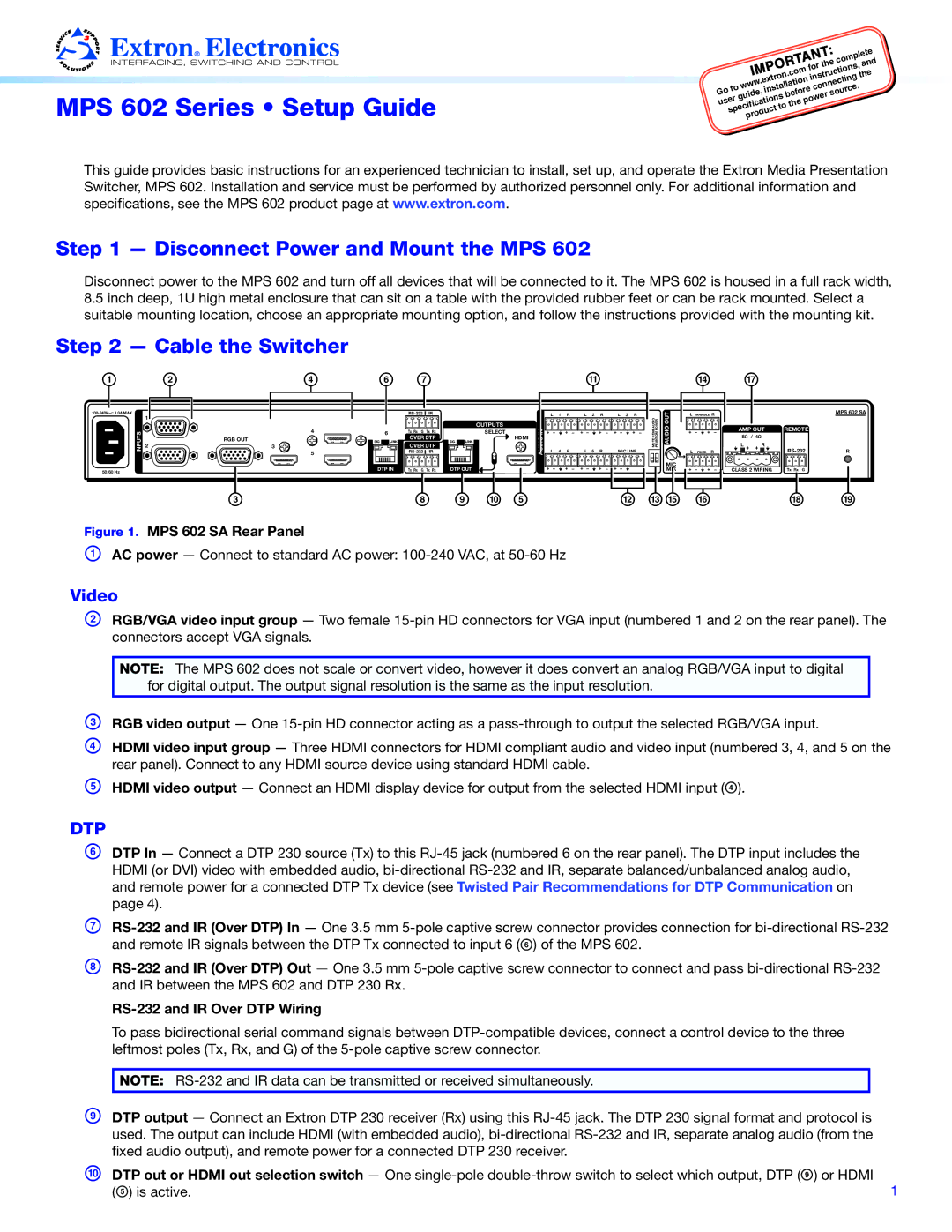
Figure 1. MPS 602 SA Rear Panel
AAC power — Connect to standard AC power:
Video
BRGB/VGA video input group — Two female
NOTE: The MPS 602 does not scale or convert video, however it does convert an analog RGB/VGA input to digital for digital output. The output signal resolution is the same as the input resolution.
CRGB video output — One
DHDMI video input group — Three HDMI connectors for HDMI compliant audio and video input (numbered 3, 4, and 5 on the rear panel). Connect to any HDMI source device using standard HDMI cable.
EHDMI video output — Connect an HDMI display device for output from the selected HDMI input (D).
DTP
FDTP In — Connect a DTP 230 source (Tx) to this RJ‑45 jack (numbered 6 on the rear panel). The DTP input includes the HDMI (or DVI) video with embedded audio,
G
H
RS-232 and IR Over DTP Wiring
To pass bidirectional serial command signals between
NOTE:
IDTP output — Connect an Extron DTP 230 receiver (Rx) using this RJ‑45 jack. The DTP 230 signal format and protocol is used. The output can include HDMI (with embedded audio),
JDTP out or HDMI out selection switch — One
(E) is active. | 1 |