MPS 602 • Setup Guide (Continued)
Analog Audio Input
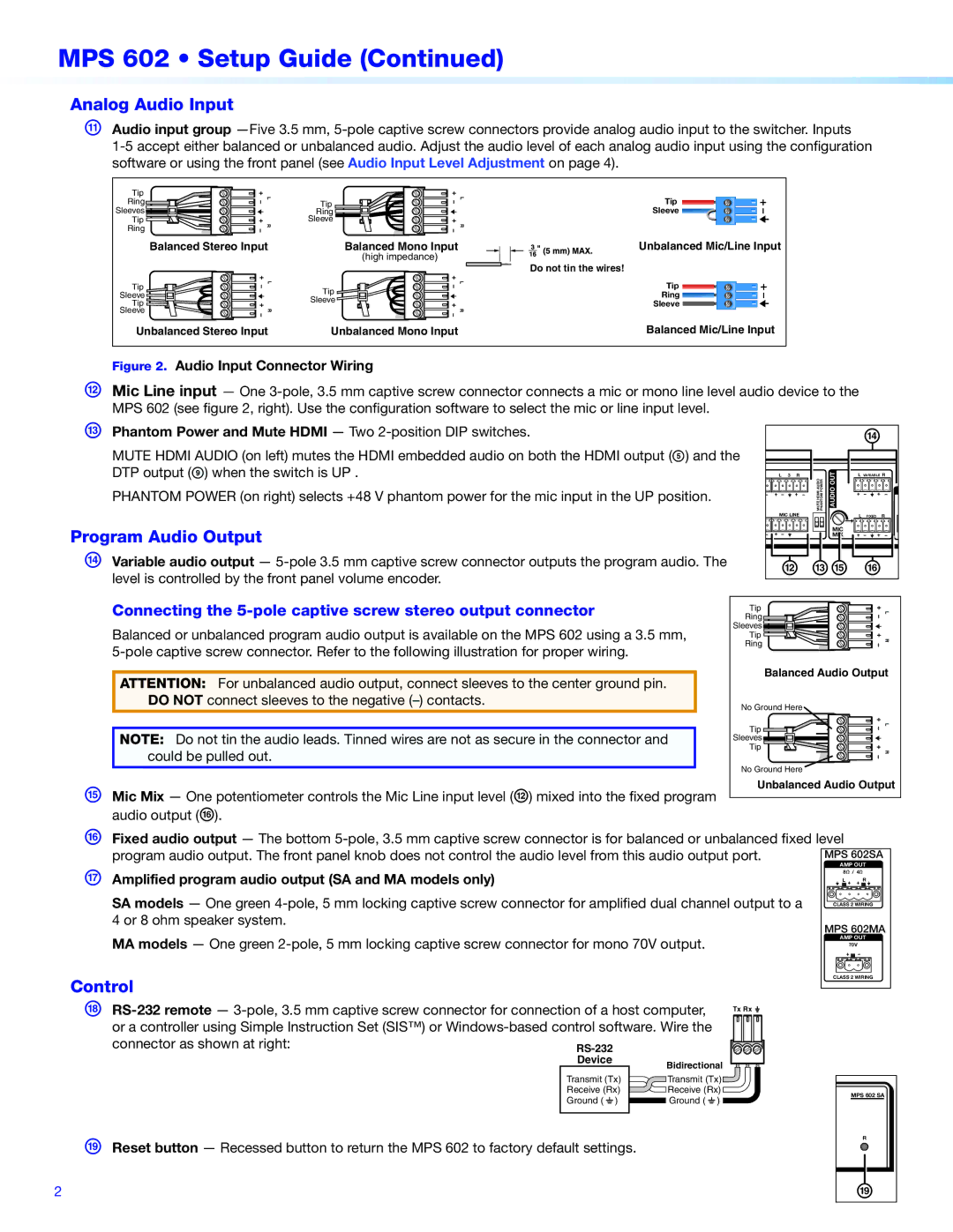
KAudio input group
Tip | L |
Ring | |
Sleeves |
|
Tip | R |
Ring |
Balanced Stereo Input
Tip | L |
| |
Sleeve |
|
Tip |
|
Sleeve | R |
Tip | L |
| |
Ring |
|
Sleeve | R |
| |
| Balanced Mono Input |
| (high impedance) |
| L |
Tip |
|
Sleeve |
|
R
Tip
Sleeve ![]()
![]()
Unbalanced Mic/Line Input
Do not tin the wires!
Tip ![]()
![]()
Ring ![]()
![]()
Sleeve
Unbalanced Stereo Input | Unbalanced Mono Input | Balanced Mic/Line Input |
Figure 2. Audio Input Connector Wiring |
|
|
|
|
|
L Mic Line input — One |
| ||||
MPS 602 (see figure 2, right). Use the configuration software to select the mic or line input level. |
|
|
|
|
|
M Phantom Power and Mute HDMI — Two |
|
|
| n |
|
MUTE HDMI AUDIO (on left) mutes the HDMI embedded audio on both the HDMI output (E) and the |
|
|
| ||
|
|
|
| ||
DTP output (I) when the switch is UP . | L 3 | R | AUDIOOUT | L VARIABLE R | |
PHANTOM POWER (on right) selects +48 V phantom power for the mic input in the UP position. |
| MUTEHDMI AUDIO PHANTOMPOWER |
|
| |
|
|
|
|
| |
| MIC LINE |
| L FIXED | R | |
Program Audio Output |
|
| MIC |
|
|
|
| MIX |
|
| |
|
|
|
|
| |
N Variable audio output — | l mo p |
| |||
level is controlled by the front panel volume encoder. |
| ||||
Connecting the | Ring |
|
|
|
|
| Tip |
|
|
| L |
Balanced or unbalanced program audio output is available on the MPS 602 using a 3.5 mm, | Sleeves |
|
|
|
|
Tip |
|
|
| R | |
Ring |
|
|
|
| |
|
|
|
|
| |
| Balanced Audio Output | |
ATTENTION: For unbalanced audio output, connect sleeves to the center ground pin. | ||
| ||
DO NOT connect sleeves to the negative | No Ground Here |
| Tip | L |
NOTE: Do not tin the audio leads. Tinned wires are not as secure in the connector and |
| |
Sleeves |
| |
could be pulled out. | Tip | R |
| ||
| No Ground Here |
|
O | Mic Mix — One potentiometer controls the Mic Line input level (L) mixed into the fixed program |
|
|
|
|
|
| Unbalanced Audio Output | ||||||||
|
|
|
|
|
|
|
|
|
|
|
|
|
|
| ||
|
|
|
|
|
|
|
|
|
|
|
|
|
|
| ||
| audio output (P). |
|
|
|
|
|
|
|
|
|
|
|
|
|
|
|
P Fixed audio output — The bottom | ||||||||||||||||
| program audio output. The front panel knob does not control the audio level from this audio output port. |
| MPS 602SA |
| ||||||||||||
|
|
|
|
|
|
|
|
|
|
|
|
| AMP OUT |
| ||
Q | Amplified program audio output (SA and MA models only) |
|
|
|
|
|
|
|
|
|
|
| 8Ω / 4Ω |
| ||
|
|
|
|
|
|
|
|
|
|
| L R |
| ||||
| SA models — One green | a |
|
|
|
|
|
| ||||||||
|
|
|
|
|
|
| ||||||||||
|
| CLASS 2 WIRING |
| |||||||||||||
| 4 or 8 ohm speaker system. |
|
|
|
|
|
|
|
|
| MPS 602MA |
| ||||
|
|
|
|
|
|
|
|
|
|
|
| |||||
| MA models — One green |
|
|
|
|
|
|
|
|
|
|
| AMP OUT |
| ||
|
|
|
|
|
|
|
|
|
|
|
| 70V |
| |||
|
|
|
|
|
|
|
|
|
|
|
|
|
|
| ||
|
|
|
|
|
|
|
|
|
|
|
|
|
|
|
|
|
Control |
|
|
|
|
|
|
|
|
|
| CLASS 2 WIRING |
| ||||
|
|
|
|
|
|
|
|
|
|
|
|
|
|
| ||
|
|
|
|
|
|
|
|
|
|
|
|
|
|
| ||
R | Tx Rx |
|
|
|
|
|
|
| ||||||||
| or a controller using Simple Instruction Set (SIS™) or |
|
|
|
|
|
|
|
|
|
|
|
|
|
|
|
|
|
|
|
|
|
|
|
|
|
|
|
|
|
|
| |
|
|
|
|
|
|
|
|
|
|
|
|
|
|
|
| |
| connector as shown at right: |
|
|
|
|
|
|
|
|
|
|
|
|
|
|
|
|
|
|
|
|
|
|
|
|
|
|
|
|
|
|
| |
Bidirectional
Transmit (Tx)
Receive (Rx)
![]()
![]() Ground ( _ )
Ground ( _ )
SReset button — Recessed button to return the MPS 602 to factory default settings.
2
MPS 602 SA
R
s
