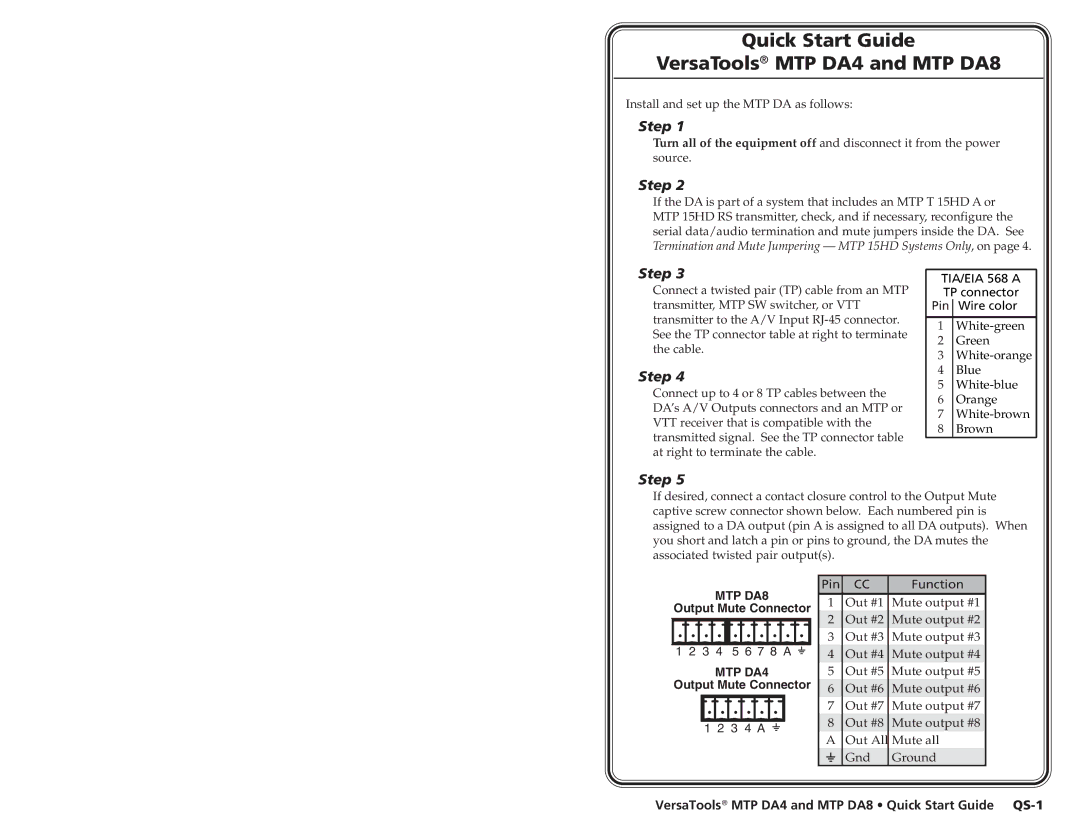
MTP DA4, MTP DA8 specifications
Extron Electronics is a leading manufacturer of high-performance AV distribution systems, and its MTP DA4 and MTP DA8 products exemplify the company's commitment to quality and innovation in the field of audio-visual solutions. These distribution amplifiers, designed for multi-channel applications, offer exceptional performance with their advanced technologies and features tailored to meet professional AV needs.The MTP DA4 and MTP DA8 are designed to distribute HDBaseT signals over long distances, making them ideal for classrooms, conference rooms, and large venues where reliable signal transmission is crucial. With the capability of supporting resolutions up to 4K, both models ensure that the highest quality video and audio are maintained across all connected displays. This is particularly important in environments that rely on clear and detailed presentations.
One of the standout features of both models is their ability to simultaneously drive multiple outputs while maintaining signal integrity. The MTP DA4 supports four outputs, while the MTP DA8 expands this capability to eight outputs. This allows users to connect multiple displays from a single source without any loss of quality. Additionally, each output is independently buffered, ensuring that signals remain strong and distortion-free.
Technologically, the MTP DA4 and MTP DA8 utilize Extron's proprietary circuitry designed for superior signal processing. With features such as automatic equalization and cable compensation, these devices enhance performance by adjusting to varying cable lengths and types. This means that whether a setup is using standard cable or extended lengths, the MTP DAs ensure optimal signal quality.
Furthermore, both units are equipped with user-friendly features such as LED indicators that provide real-time feedback on power and signal status, making troubleshooting efficient. They also support various input formats, allowing for flexible integration with existing AV systems. The compact design of these distribution amplifiers makes them easy to install in a variety of environments, ensuring that space constraints do not hinder performance.
In summary, the Extron MTP DA4 and MTP DA8 distribution amplifiers offer robust features designed for high-quality AV distribution. Their advanced signal processing capabilities, expandable outputs, and user-friendly design make them ideal solutions for professional audio-visual applications. Whether for educational environments, corporate settings, or live events, these products ensure reliable performance and clarity.

