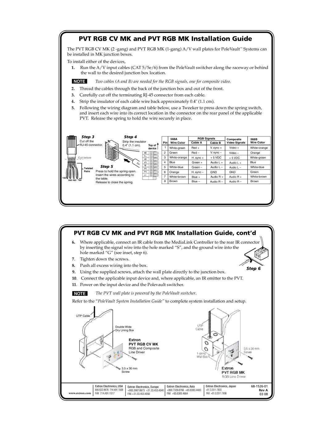
PVT RGB MK, PVT RGB CV MK specifications
Extron Electronics is a prominent player in the field of audiovisual (AV) technology, and its PVT RGB MK and PVT RGB CV MK series represent some of the cutting-edge solutions the company offers for signal management in professional AV environments. These products are specifically designed to provide seamless integration, high performance, and user-friendly functionality ideal for various applications ranging from corporate environments to educational institutions.The PVT RGB MK model is engineered to handle RGB video signals with exceptional precision and fidelity. It supports a wide range of resolutions including standard VGA, as well as higher resolutions up to 1920x1200. This ensures that whatever the source, the output maintains a crystal-clear image. The device also incorporates advanced signal processing technology that not only enhances image quality but also minimizes signal loss over long cable runs.
Meanwhile, the PVT RGB CV MK model expands the capabilities of the series by integrating composite video alongside RGB support. This versatility makes it an excellent choice for situations where both types of signals may be present. It accommodates various input formats and enables the user to switch seamlessly between RGB and composite video sources without degradation in quality.
Both models are equipped with Extron’s proprietary EDID management, enabling optimal configuration for connected devices and ensuring that the source and display maintain compatibility. This feature facilitates easy installation and setup, reducing the number of potential issues arising from mismatched display settings.
Moreover, the intuitive user interface and a variety of control options including front panel buttons, RS-232, and a web-based interface offer users flexibility in managing signals. The integration of Extron’s exclusive Fast Switching Technology further enhances usability, allowing for rapid source changes with no noticeable delay.
In terms of build quality, both the PVT RGB MK and PVT RGB CV MK are constructed to meet high standards of durability and reliability. They are designed to withstand the demands of professional use while maintaining a sleek, compact footprint that fits easily within any AV rack or installation kit.
Overall, the Extron PVT RGB MK and PVT RGB CV MK models provide robust and flexible solutions for AV signal management, with features that cater to the needs of modern applications, making them indispensable tools for AV professionals.