RGB 202 VS SL2, RGB 202 VTG, RGB 202 VS2 specifications
Extron Electronics has long been a leader in the field of AV solutions, and their RGB 202 series continues to exemplify industry excellence. The RGB 202 VS2, RGB 202 VTG, and RGB 202 VS SL2 are part of this distinguished series, each offering unique features and technologies designed to elevate video signal management for various applications.The Extron RGB 202 VS2 is a high-performance video switcher that supports multiple RGBHV inputs. It allows seamless switching between various video sources, making it ideal for presentations and live events. Equipped with advanced technology, the VS2 includes features such as automatic input detection, which simplifies user interaction and minimizes setup time. Furthermore, its integrated scaling capabilities ensure that output resolutions are matched with display devices, delivering optimal image quality regardless of source format.
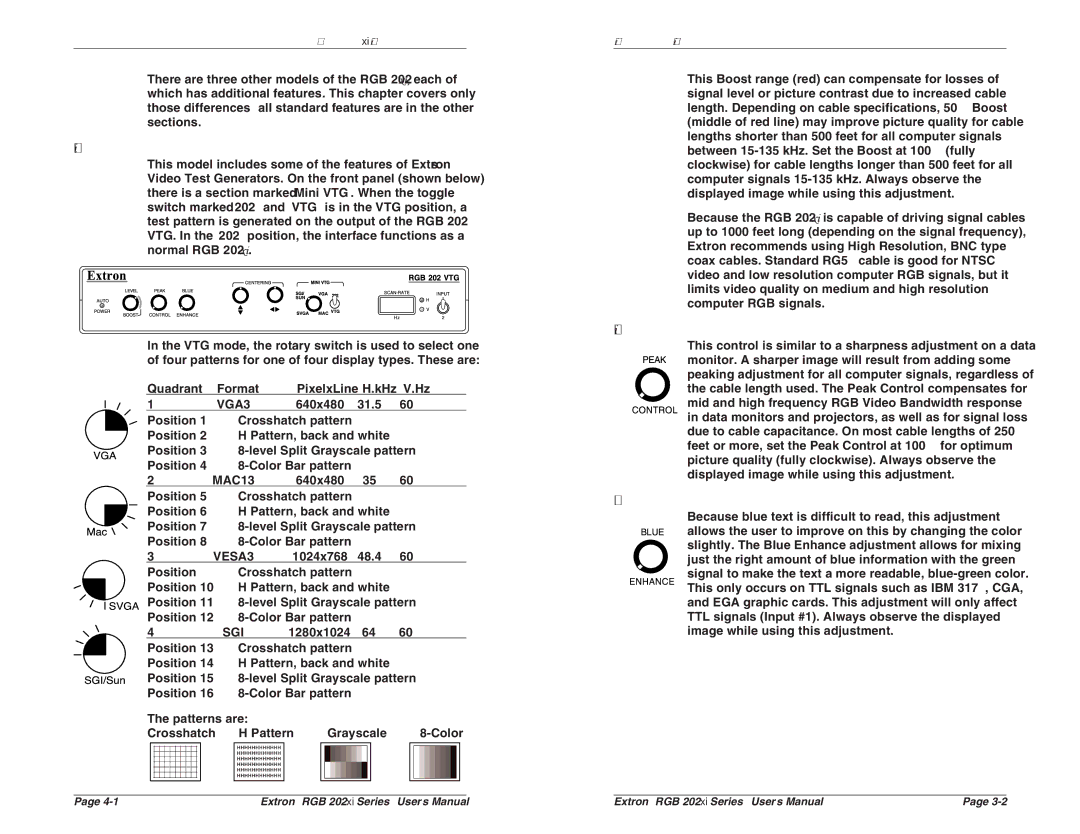
The RGB 202 VTG specializes in pristine video signal generation, making it a perfect companion for professionals in need of a reliable test signal generator. It offers a variety of standard video test patterns, including color bars and grayscale, allowing users to assess and calibrate the performance of their display systems accurately. Furthermore, the VTG supports both RGB and component video signals, ensuring versatility in connectivity.
The RGB 202 VS SL2 is another standout model, focused on advanced signal processing. This versatile switcher is designed to handle various input formats, including RGB, composite, and component video, providing unmatched flexibility for users. It features a sophisticated video enhancement algorithm that optimizes color, brightness, and clarity, resulting in an exceptional viewing experience.
All models in the RGB 202 series come equipped with Extron’s renowned EDID and HDCP compliance technology, which ensures compatibility with a wide range of digital and analog devices. The user-friendly interface and intuitive control options further enhance ease of use, allowing operators to focus on content rather than managing technical complexities.
Ultimately, the Extron RGB 202 VS2, RGB 202 VTG, and RGB 202 VS SL2 embody the brand’s commitment to quality and innovation in AV technology. Whether for a corporate environment, educational institution, or live event, these products provide the reliability and performance that professionals demand in today’s fast-paced visual communications landscape.