Installation and Operation
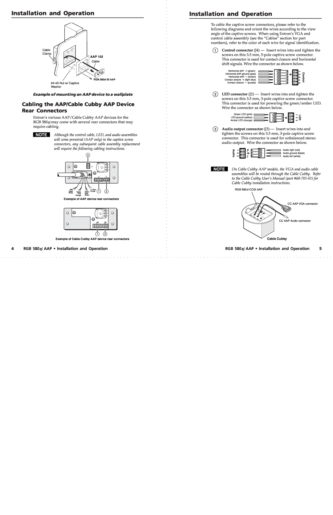
Cable
Clamp
AAP 102
Cable
AAP | 102 |
|
RGB 580xi SI AAP
Example of mounting an AAP device to a wallplate
Cabling the AAP/Cable Cubby AAP Device Rear Connectors
Extron’s various AAP/Cable Cubby AAP devices for the RGB 580xi may come with several rear connectors that may require cabling.
Although the control cable, LED, and audio assemblies will come prewired (AAP only) to the captive screw connectors, any subsequent cable assembly replacement will require the following cabling instructions.
3
|
| J3 |
|
|
|
|
| J4 | J2 |
Red |
| Lt. Blue | 1 | 2 |
Black | Yellow | Green Purple | ||
White | Pink | Gray |
|
|
| Orange | Brown |
|
|
Example of AAP device rear connectors
J4 J2
1 2
Example of Cable Cubby AAP device rear connectors
Installation and Operation
To cable the captive screw connectors, please refer to the following diagrams and orient the wires according to the view angle of the captive screws. When using Extron’s VGA and control cable assembly (see the “Cables” section for part numbers), refer to the color of each wire for signal identification.
1Control connector (J4) — Insert wires into and tighten the screws on this 3.5 mm,
Horizontal shift | + (green) | 1 | Control |
Horizontal shift ground (gray) | 2 3 4 5 | ||
Horizontal shift | – (brown) | ||
Contact closure + (light blue) | |||
Contact closure | – (purple) | ||
2LED connector (J2) — Insert wires into and tighten the screws on this 3.5 mm,
Green LED (pink) | 1 23 | LED |
LED ground (yellow) | ||
Amber LED (orange) |
|
|
3Audio output connector (J3) — Insert wires into and tighten the screws on this 3.5 mm,
Audio | 1 23 | R+ | Audio right (red) |
L+ | Audio ground (black) | ||
|
|
| Audio left (white) |
On Cable Cubby AAP models, the VGA and audio cable assemblies will be routed through the Cable Cubby. Refer to the Cable Cubby User’s Manual (part
RGB 580xi CCSI AAP
CC AAP VGA connector
CC AAP Audio connector
Cable Cubby
4 | RGB 580xi AAP • Installation and Operation | RGB 580xi AAP • Installation and Operation | 5 |