Installation and Operation
Extron’s RGB 580xi AAP
RGB 580xi AAP/CC AAP Series Features
RGB 580xi AAP | 3 | 4 |
| 3 |
|
|
| RGB 580xi S AAP | |
| AUDIO IN | SHIFT |
| AUDIO IN |
| COMPUTER IN |
|
| COMPUTER IN |
| RGB 580xi |
|
| RGB 580xi |
1 | 2 | 1 | 2 |
|
|
| 4 |
| 3 |
|
|
|
| RGB 580xi SI AAP |
|
| SHIFT | SELECT | AUDIO IN |
|
|
|
COMPUTER IN
RGB 580xi
Installation and Operation
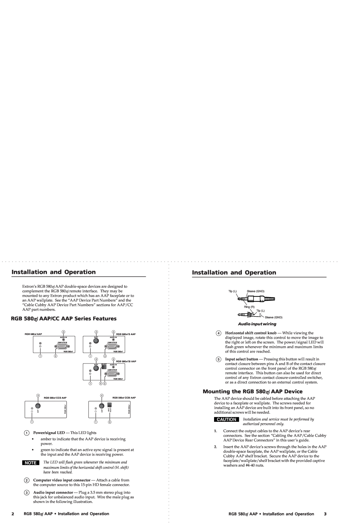
Tip (L) | Sleeve (GND) |
Ring (R)
Tip (L)
Sleeve (GND)
Audio input wiring
| 4 Horizontal shift control knob — While viewing the |
displayed image, rotate this control to move the image to |
the right or left on the screen. The power/signal LED will |
flash green whenever the minimum and maximum limits |
of this control are reached. |
5 Input select button — Pressing this button will result in |
contact closure between pins A and B of the contact closure |
control connector on the front panel of the RGB 580xi |
remote interface. This button can also be used for direct |
control of any Extron contact |
or as a direct connection to an external control system. |
1
4 | RGB 580xi CCS AAP |
| |
SHIFT | 580xi |
RGB |
5 | 2 |
|
4 |
| RGB 580xi CCSI AAP |
|
| |
SHIFT | INPUT SELECT | RGB 580xi |
Mounting the RGB 580xi AAP Device
The AAP device should be cabled before attaching the AAP device to a faceplate or wallplate. The screws needed for installing an AAP device are built into its front panel, so no additional screws will be needed.
1 | 1 | 5 |
•amber to indicate that the AAP device is receiving power.
•green to indicate that an active sync signal is present at the input and the AAP device is receiving power.
The LED will flash green whenever the minimum and maximum limits of the horizontal shift control (H. shift) have been reached.
2Computer video input connector — Attach a cable from the computer source to this
3Audio input connector — Plug a 3.5 mm stereo plug into this jack for unbalanced audio input. Wire the male plug as shown in the following illustration.
CAUTION | Installation and service must be performed by | |
|
| authorized personnel only. |
1. | Connect the output cables to the AAP device’s rear | |
| connectors. See the section “Cabling the AAP/Cable Cubby | |
| AAP Device Rear Connectors” in this user’s guide. | |
2. | Insert the AAP device’s screws through the holes in the AAP | |
|
| |
| Cubby AAP shelf bracket. Secure the AAP device to the | |
faceplate/wallplate/shelf bracket with the provided captive washers and
2 | RGB 580xi AAP • Installation and Operation | RGB 580xi AAP • Installation and Operation | 3 |