SW USB Series, RSB 126, RSU 126, RSB129, RSF123 specifications
Extron Electronic is a well-known brand in the AV industry, renowned for its high-quality signal distribution, control systems, and mounting solutions. Among its impressive range of products, the RSB129, RSF123, RSU 126, RSB 126, and SW USB Series stand out due to their sophisticated features and technologies.The RSB129 is a robust rack shelf designed to accommodate a variety of equipment, such as routers, switches, and other AV devices. This shelf can support up to 300 pounds, making it an excellent choice for heavy-duty applications. It also features adjustable mounting points that allow for flexible placement of devices, ensuring an organized and efficient setup.
The RSF123, on the other hand, is a flexible rack frame solution that provides a reliable mounting option for intermediate size equipment. This 2U rack frame is built to hold devices securely, while its front ventilation design aids in maintaining optimal temperature levels. The RSF123 is particularly popular for those looking to streamline their installations with a clean and professional aesthetic.
The RSU 126 is another versatile rack mount solution that focuses on aesthetic appeal while providing functionality. Designed for environments where aesthetics matter, the RSU 126 features a smooth, sleek design that integrates seamlessly into office and conference room settings. Its compact 2U size makes it suitable for various AV applications, while its durable build ensures long-lasting use.
The RSB 126 is similar in nature to the RSB129 but is crafted for smaller setups. This 1U rack shelf is ideal for less intensive applications but still boasts impressive weight support. It features a front lip that prevents equipment from sliding off, ensuring that devices are kept securely in place. The RSB 126 is perfect for studios, server rooms, or any location requiring a compact yet sturdy shelf.
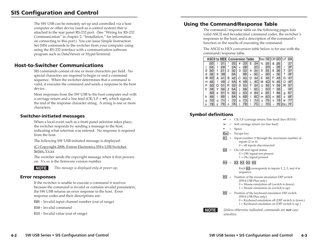
Finally, the SW USB Series is a suite of USB products designed to streamline connectivity in modern AV installations. These USB devices offer flexible options for extending USB signals over long distances without loss of quality. They support a variety of USB protocols, making them compatible with numerous devices, from cameras to computers. The SW USB Series aims to simplify complex installations, ensuring a reliable connection in various environments.
In summary, Extron's RSB129, RSF123, RSU 126, RSB 126, and SW USB Series products cater to a variety of AV installation needs, combining durability, functionality, and aesthetics. Whether for heavy-duty rack shelving or streamlined USB connectivity, these products are designed to enhance any AV setup.

