IntroductionductionandandInstallInstallationtion, cont’d
About the SCP 100P
The Extron SCP 100P control panel replicates the front panel controls of the Extron System 5cr Plus system switcher, and it is also compatible with the System 5cr switcher. The Input 3 button on the control panel corresponds to the PC3 button on the front panel of the System 5cr. Up to two SCP 100Ps can be connected to the System 5cr/5cr Plus.
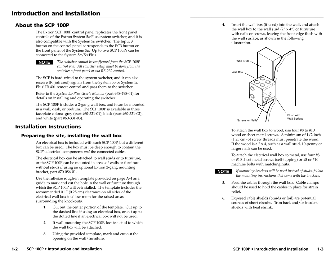
4.Insert the wall box (if used) into the wall, and attach the wall box to the wall stud (2” x 4”) or furniture with nails or screws, leaving the front edge flush with the wall surface, as shown in the following illustration.
The switcher cannot be configured from the SCP 100P control pad. All switcher setup must be done from the switcher’s front panel or via
The SCP is
Refer to the System 5cr Plus User’s Manual (part
The SCP 100P includes a
Installation Instructions
Wall Stud
Wall Box
Screws or Nails
Flush with Wall Surface
Preparing the site, installing the wall box
An electrical box is included with each SCP 100P, but a different box can be used. The box must be deep enough to contain the SCP’s electrical components and the connected cables.
The electrical box can be attached to wall studs or to furniture, or the SCP 100P can be mounted in areas of walls or furniture without studs if using an optional Extron
Use the
1.Cut out the center portion of the template. Cut up to the dashed line if using an electrical box, or cut up to the dotted line if an electrical box will not be used.
2.If
3.Using the provided template, mark and cut out the opening on the wall/furniture.
To attach the wall box to wood, use four #8 to #10 wood or sheet metal screws. A minimum of 1/2 inch (1.25 cm) of screw threads must penetrate the wood. If the wood is a 2 x 4, such as a wall stud,
To attach the electrical wall box to metal, use four #8 or #10 sheet metal screws
If mounting brackets will be used instead of studs, follow the mounting instructions that came with the brackets.
5.Feed the cables through the wall box. Cable clamps should be used to hold the cables in place for strain relief.
6.Exposed cable shields (braids or foil) are potential sources of short circuits. Trim back and/or insulate shields with heat shrink.
SCP 100P • Introduction and Installation | SCP 100P • Introduction and Installation |