Installation and Operation

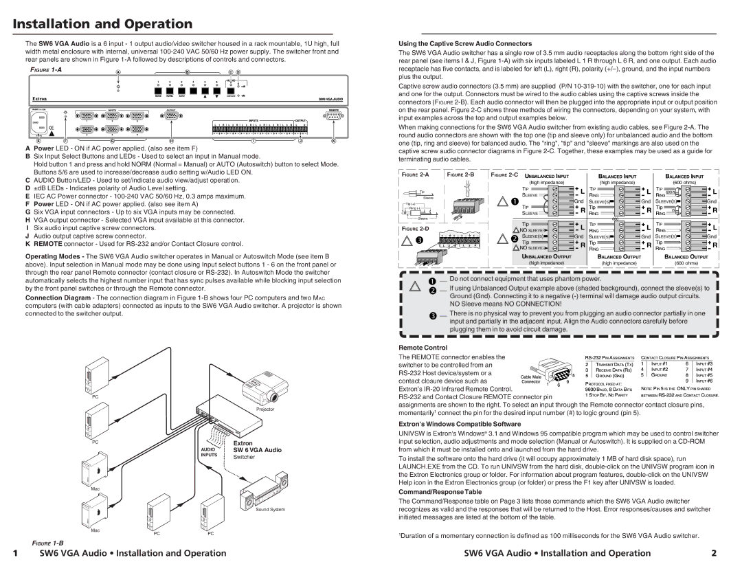
The SW6 VGA Audio is a 6 input - 1 output audio/video switcher housed in a rack mountable, 1U high, full width metal enclosure with internal, universal 100-240 VAC 50/60 Hz power supply. The switcher front and rear panels are shown in Figure 1-A followed by descriptions of controls and connectors.

FIGURE 1-A

A

Power LED - ON if AC power applied. (also see item F)

B Six Input Select Buttons and LEDs - Used to select an input in Manual mode.


Hold button 1 and press and hold NORM (Normal = Manual) or AUTO (Autoswitch) button to select Mode.


Buttons 5/6 are used to increase/decrease audio setting w/Audio LED ON.

Using the Captive Screw Audio Connectors

The SW6 VGA Audio switcher has a single row of 3.5 mm audio receptacles along the bottom right side of the rear panel (see items I & J, Figure 1-A) with six inputs labeled L 1 R through L 6 R, and one output. Each audio receptacle has five contacts, and is labeled for left (L), right (R), polarity (+/–), ground, and the input numbers plus the output.

Captive screw audio connectors (3.5 mm) are supplied (P/N 10-319-10) with the switcher, one for each input and one for the output. Connectors must be wired to the audio cables using the captive screws inside the connectors (FIGURE 2-B). Each audio connector will then be plugged into the appropriate input or output position on the rear panel. Figure 2-C shows three methods of wiring the connectors, depending on your system, with input examples across the top and output examples below.

When making connections for the SW6 VGA Audio switcher from existing audio cables, see Figure 2-A. The round audio connectors are shown with the top one (tip and sleeve only) for unbalanced audio and the bottom one (tip, ring and sleeve) for balanced audio. The "ring", "tip" and "sleeve" markings are also used on the captive screw audio connector diagrams in Figure 2-C. Together, these examples may be used as a guide for terminating audio cables.

C

AUDIO Button/LED - Used to set/indicate audio view/adjust operation.

D

±dB LEDs - Indicates polarity of Audio Level setting.

E

IEC AC Power connector - 100-240 VAC 50/60 Hz, 0.3 amps maximum.

F

Power LED - ON if AC power applied. (also see item A)

G

Six VGA input connectors - Up to six VGA inputs may be connected.

H

VGA output connector - Selected VGA input available at this connector.

ISix audio input captive screw connectors. J Audio output captive screw connector.

K REMOTE connector - Used for RS-232 and/or Contact Closure control.

Operating Modes - The SW6 VGA Audio switcher operates in Manual or Autoswitch Mode (see item B above). Input selection in Manual mode may be done using Input select buttons 1 - 6 on the front panel or through the rear panel Remote connector (contact closure or RS-232). In Autoswitch Mode the switcher

FIGURE 2-A

FIGURE 2-B

Tip

Sleeve

Tip (+)

Ring (-)

Sleeve

FIGURE 2-D

L

2

R

L

3

R

FIGURE 2-CUNBALANCED INPUT

BALANCED INPUT

BALANCED INPUT

(high impedance)


(high impedance)


(600 ohms)


TIP


TIP


TIP


SLEEVE

L RING

L

600

L

RING

TIP

Gnd SLEEVE(S)

Gnd SLEEVE(S)

Gnd

R

Tip

R

Tip

R

SLEEVE


RING


RING


600


TIP


Tip

L

TIP

L

L

NO SLEEVE

RING

RING

SLEEVE(S)

Gnd SLEEVE(S)

Gnd SLEEVE(S)

Gnd

Tip

R

Tip

R

Tip

R

NO SLEEVE


RING


RING


UNBALANCED OUTPUT

BALANCED OUTPUT


BALANCED OUTPUT


(high impedance)


(high impedance)


(600 ohms)


automatically selects the highest number input that has sync pulses available while blocking input selection by the front panel switches or through the Remote connector.

Connection Diagram - The connection diagram in Figure 1-B shows four PC computers and two MAC computers (with cable adapters) connected as inputs to the SW6 VGA Audio switcher. A projector is shown connected to the switcher output.

PC


Projector

PC

Extron

AUDIO

SW 6 VGA Audio

INPUTS

Switcher


__ Do not connect equipment that uses phantom power.

__ If using Unbalanced Output example above (shaded background), connect the sleeve(s) to Ground (Gnd). Connecting it to a negative (-) terminal will damage audio output circuits. NO Sleeve means NO CONNECTION!

__ There is no physical way to prevent you from plugging an audio connector partially in one input and partially in the adjacent input. Align the Audio connectors carefully before plugging them in to avoid circuit damage.

Remote Control

The REMOTE connector enables the switcher to be controlled from an RS-232 Host device/system or a contact closure device such as Extron’s IR-20 Infrared Remote Control. RS-232 and Contact Closure REMOTE connector pin assignments are shown to the right. To select an input through the Remote connector contact closure pins, momentarily1 connect the pin for the desired input number (#) to logic ground (pin 5).

Extron's Windows Compatible Software

UNIVSW is Extron's Windows® 3.1 and Windows 95 compatible program which may be used to control switcher input selection, audio adjustments and mode selection (Manual or Autoswitch). It is supplied on a CD-ROM from which it must be installed onto and launched from the hard drive.

To install the software onto the hard drive (it will occupy approximately 1 MB of hard disk space), run LAUNCH.EXE from the CD. To run UNIVSW from the hard disk, double-click on the UNIVSW program icon in the Extron Electronics group or folder. For information about program features, double-click on the UNIVSW Help icon in the Extron Electronics group (or folder) or press the F1 key after UNIVSW is loaded.

Mac

Mac

FIGURE 1-B

Sound System

PCPC

Command/Response Table

The Command/Response table on Page 3 lists those commands which the SW6 VGA Audio switcher recognizes as valid and the responses that will be returned to the Host. Error responses/causes and switcher initiated messages are listed at the bottom of the table.

1Duration of a momentary connection is defined as 100 milliseconds for the SW6 VGA Audio switcher.

1

SW6 VGA Audio • Installation and Operation

SW6 VGA Audio • Installation and Operation

2

Page 2
Image 2
Extron electronic SW6 specifications Installation and Operation

SW6 specifications

Extron Electronics is renowned for its innovative solutions in the audiovisual (AV) industry. Among its extensive range of products, the SW6 and SW8 series stand out as versatile audio/video switchers designed to streamline the process of managing multiple AV sources.

The Extron SW6 and SW8 are classified as standalone switchers that cater to various application needs, making them particularly suitable for classrooms, conference rooms, and control rooms. The SW6 model allows for the switching of up to six AV sources, while the SW8 model expands this capability to eight sources. This flexibility is crucial in environments where multiple devices need to be connected seamlessly, enhancing productivity and collaboration.

One of the main features of the SW6 and SW8 switchers is their input versatility. They can accommodate a wide array of video formats, including HDMI, VGA, and composite video, ensuring compatibility with older and newer devices alike. Furthermore, both models support audio formats, allowing for the integration of both video and sound sources in a single unit. The switchers typically include audio embedding, which seamlessly combines audio from a chosen source with the video output, enabling streamlined audio and video transmission.

In terms of technology, the Extron SW6 and SW8 devices incorporate advanced switching technology that ensures reliable signal management with minimal latency. Setting them apart is their ability to support features like automatic input switching, allowing users to enjoy an uninterrupted viewing experience without the need for manual intervention. The included RS-232 and Ethernet control capabilities also provide flexibility for integration into larger control systems, enhancing their functionality within complex AV setups.

Additionally, both the SW6 and SW8 series are designed with user-friendly interfaces. Front-panel push buttons allow for intuitive operation, while remote control options give flexibility for integration into existing systems. The units also feature status indicators, providing users with real-time feedback on the currently selected input, making operation straightforward even for non-technical users.

In conclusion, the Extron SW6 and SW8 audio/video switchers are essential tools for managing multiple AV sources with ease. Their versatility in handling various input formats, advanced switching technology, and user-friendly design make them ideal for a range of applications. Whether in an educational setting or a corporate environment, these switchers deliver superior performance and reliability, affirming Extron’s commitment to excellence in the audiovisual landscape.