VNR 100 specifications
Extron Electronics has been a leader in the professional AV industry for over three decades, and their VNR 100 is a notable addition to their extensive product lineup. The VNR 100 is a versatile video network receiver designed to provide high-quality video and audio streaming over standard network infrastructure, making it an essential tool for modern AV installations.One of the main features of the VNR 100 is its ability to support not just standard video formats, but also high-definition resolutions up to 4K. This ensures that users can enjoy crystal-clear image quality, regardless of the source. The device seamlessly integrates with Extron's XTP Systems, allowing it to receive video and audio signals from various sources distributed over a network. Additionally, the VNR 100 is designed to accommodate a wide range of video sources, including PCs, video conferencing systems, and media players, making it an ideal solution for diverse environments.
The VNR 100 employs advanced technologies such as Extron's proprietary AV over IP technology, which ensures efficient video and audio transmission with minimal latency. This is particularly crucial in environments where real-time communication or interaction is required, such as educational institutions and corporate settings. The device also features built-in scaling capabilities, allowing users to adjust output resolutions to fit specific display requirements.
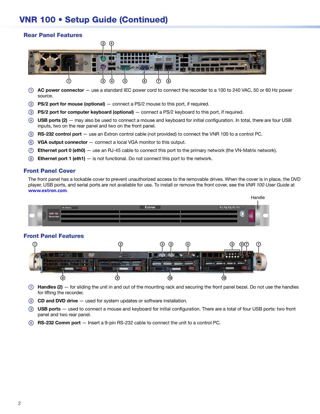
Adding to its flexibility, the VNR 100 includes multiple connectivity options, including HDMI, RS-232, and USB. This array of connections facilitates easy integration with existing AV systems and simplifies setup and operation. The device is also equipped with comprehensive control options, including the ability to be managed through Extron's Global Viewer Enterprise software, offering remote monitoring and control capabilities.
Further enhancing its appeal, the VNR 100 is designed with a compact form factor, making it suitable for both rack-mounted and standalone installations. It features a robust build quality and is engineered for reliability, ensuring continuous operation in demanding environments.
In conclusion, the Extron VNR 100 video network receiver stands out for its impressive capabilities and flexibility in modern AV applications. Whether in educational, corporate, or hospitality environments, the VNR 100 delivers top-notch performance, ensuring high-quality audio and video distribution while providing simplified integration and control. Its broad compatibility and advanced features make it an excellent choice for today’s advanced AV systems.

