WPC 160 A Series • Installation Guide (Continued)
VGA and TRS Connections
TRS | Captive Screw Pin | Color | |
|
|
|
|
1 Red* |
| R | Red coax |
|
|
|
|
2 Green* |
| G | Green coax |
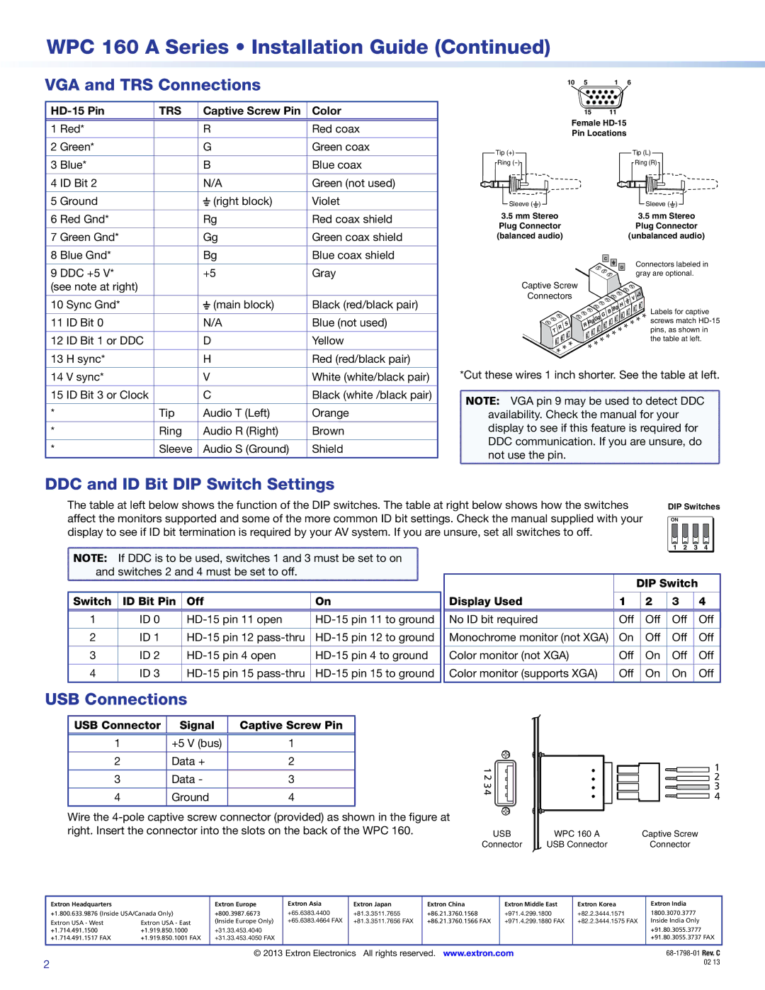
10 | 5 | 1 | 6 |
15 11
Female
3 | Blue* | B | Blue coax | |||
|
|
|
|
|
| |
4 | ID Bit 2 | N/A | Green (not used) | |||
|
|
|
|
|
| |
5 | Ground |
|
| (right block) | Violet | |
|
| |||||
|
| |||||
|
|
|
|
|
| |
6 | Red Gnd* | Rg | Red coax shield | |||
|
|
|
|
|
| |
7 | Green Gnd* | Gg | Green coax shield | |||
|
|
|
|
|
| |
8 | Blue Gnd* | Bg | Blue coax shield | |||
|
|
|
|
| ||
9 DDC +5 V* | +5 | Gray | ||||
(see note at right) |
|
|
|
| ||
|
|
|
|
|
| |
10 | Sync Gnd* |
|
| (main block) | Black (red/black pair) | |
|
| |||||
|
| |||||
|
|
|
|
|
| |
11 | ID Bit 0 | N/A | Blue (not used) | |||
|
|
|
|
|
| |
12 | ID Bit 1 or DDC | D | Yellow | |||
|
|
|
|
|
| |
13 | H sync* | H | Red (red/black pair) | |||
Tip (+)
Ring
Sleeve (![]() )
) ![]()
3.5mm Stereo Plug Connector (balanced audio)
Captive Screw
Connectors
| R | S |
T |
| |
|
|
* *
Tip (L)
Ring (R)
Sleeve (![]() )
) ![]()
3.5mm Stereo Plug Connector
|
|
|
|
|
| (unbalanced audio) | |||
|
|
|
|
|
|
|
|
|
|
| C |
|
|
|
|
| Connectors labeled in | ||
|
|
|
|
| D |
| |||
|
|
|
|
|
|
| gray are optional. | ||
|
|
|
|
|
|
|
|
|
|
|
|
|
|
|
| V | +5 |
|
|
|
|
| Bg | H |
|
| Labels for captive | ||
|
|
|
|
|
| ||||
|
| B |
|
|
| * | |||
gG |
|
|
| * * * | |||||
|
|
|
| screws match | |||||
G |
|
|
|
|
| ||||
RRg | * * * |
| pins, as shown in | ||||||
* * * |
|
|
| the table at left. | |||||
|
|
|
|
|
|
|
|
| |
14 V sync* |
| V | White (white/black pair) |
|
|
|
|
15 ID Bit 3 or Clock |
| C | Black (white /black pair) |
|
|
|
|
* | Tip | Audio T (Left) | Orange |
|
|
|
|
* | Ring | Audio R (Right) | Brown |
|
|
|
|
* | Sleeve | Audio S (Ground) | Shield |
*Cut these wires 1 inch shorter. See the table at left.
NOTE: VGA pin 9 may be used to detect DDC |
availability. Check the manual for your |
display to see if this feature is required for |
DDC communication. If you are unsure, do |
not use the pin. |
DDC and ID Bit DIP Switch Settings
The table at left below shows the function of the DIP switches. The table at right below shows how the switches | DIP Switches | ||||||||
affect the monitors supported and some of the more common ID bit settings. Check the manual supplied with your | ON | ||||||||
display to see if ID bit termination is required by your AV system. If you are unsure, set all switches to off. |
|
|
|
|
|
|
|
|
|
|
|
|
|
|
|
| 1 | 2 | 3 | 4 |
NOTE: If DDC is to be used, switches 1 and 3 must be set to on |
|
|
|
|
|
|
| |||
and switches 2 and 4 must be set to off. |
|
|
| DIP Switch |
| |||||
|
|
|
|
|
|
| ||||
Switch | ID Bit Pin | Off | On | Display Used | 1 | 2 | 3 |
|
| 4 |
1 | ID 0 | No ID bit required | Off | Off | Off |
| Off | |||
2 | ID 1 | Monochrome monitor (not XGA) | On | Off | Off |
| Off | |||
3 | ID 2 | Color monitor (not XGA) | Off | On | Off |
| Off | |||
4 | ID 3 | Color monitor (supports XGA) | Off | On | On |
| Off | |||
USB Connections
USB Connector | Signal | Captive Screw Pin |
|
|
|
1 | +5 V (bus) | 1 |
|
|
|
2 | Data + | 2 |
|
|
|
3 | Data - | 3 |
|
|
|
4 | Ground | 4 |
|
|
|
Wire the
1234 |
|
USB | WPC 160 A |
Connector | USB Connector |
1
![]() 2
2
![]() 3
3 ![]() 4
4
Captive Screw
Connector
Extron Headquarters |
| Extron Europe | Extron Asia | Extron Japan | Extron China | Extron Middle East | Extron Korea | Extron India |
+1.800.633.9876 (Inside USA/Canada Only) | +800.3987.6673 | +65.6383.4400 | +81.3.3511.7655 | +86.21.3760.1568 | +971.4.299.1800 | +82.2.3444.1571 | 1800.3070.3777 | |
Extron USA - West | Extron USA - East | (Inside Europe Only) | +65.6383.4664 FAX | +81.3.3511.7656 FAX | +86.21.3760.1566 FAX | +971.4.299.1880 FAX | +82.2.3444.1575 FAX | Inside India Only |
+1.714.491.1500 | +1.919.850.1000 | +31.33.453.4040 |
|
|
|
|
| +91.80.3055.3777 |
+1.714.491.1517 FAX | +1.919.850.1001 FAX | +31.33.453.4050 FAX |
|
|
|
|
| +91.80.3055.3737 FAX |
|
|
|
|
|
|
|
|
|
© 2013 Extron Electronics All rights reserved. www.extron.com | |
2 | 02 13 |
|