
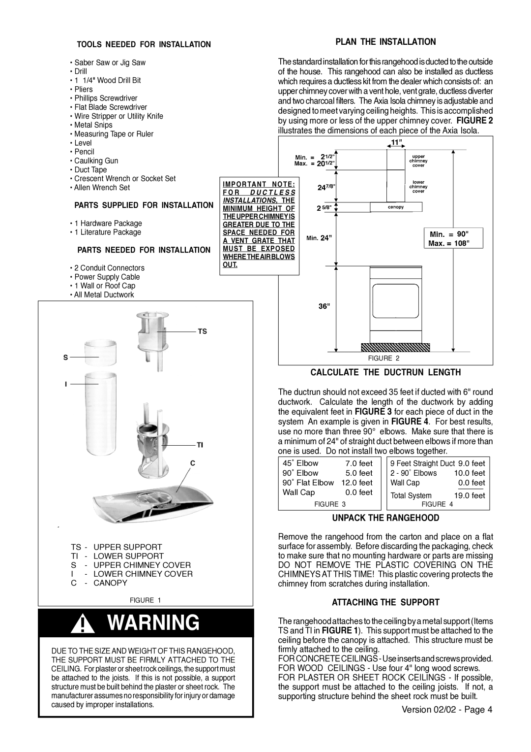
AXIA ISOLA specifications
The Faber AXIA ISOLA is a sophisticated kitchen hood that embodies the perfect blend of style, innovation, and functionality. Designed with the modern kitchen in mind, this range hood offers exceptional performance and aesthetics, making it an ideal choice for those who value both form and function in their cooking space.One of the standout features of the AXIA ISOLA is its sleek, contemporary design. It has a minimalist aesthetic that complements various kitchen styles, from ultra-modern to traditional. Available in different finishes such as stainless steel or glass, the AXIA ISOLA seamlessly integrates into any kitchen décor, serving as both a powerful ventilation solution and an eye-catching centerpiece.
The AXIA ISOLA employs cutting-edge technologies that enhance its effectiveness. One such technology is the high-performance motor, which ensures efficient air extraction, eliminating smoke, odors, and pollutants from the kitchen environment. Additionally, the hood incorporates advanced noise-reduction technologies, allowing for quiet operation even at high speeds. This makes it perfect for open concept kitchens, where cooking and socializing often happen simultaneously.
Another notable characteristic of the Faber AXIA ISOLA is its versatile installation options. Designed for both ducted and recirculating installations, the hood offers flexibility depending on kitchen layout and planning. This allows homeowners to maximize their kitchen's functionality without compromising on design.
The AXIA ISOLA features intuitive controls, often equipped with touch-sensitive buttons or remote-control functionality, allowing users to easily adjust settings from a distance. Additionally, integrated LED lighting illuminates the cooking area effectively, enhancing visibility while also being energy-efficient.
Cleaning and maintenance are also simplified, thanks to its stainless-steel construction and dishwasher-safe filters. These features reduce the effort needed to keep the hood looking and operating like new.
Overall, the Faber AXIA ISOLA is more than just a kitchen hood; it is a combination of elegance, innovation, and practicality. Perfect for culinary enthusiasts and home cooks alike, it elevates the cooking experience while ensuring a clean and fresh kitchen environment. With its advanced technologies and stylish design, the AXIA ISOLA is an investment in both the functionality and aesthetics of any modern kitchen.