RC5040, RC5042 specifications
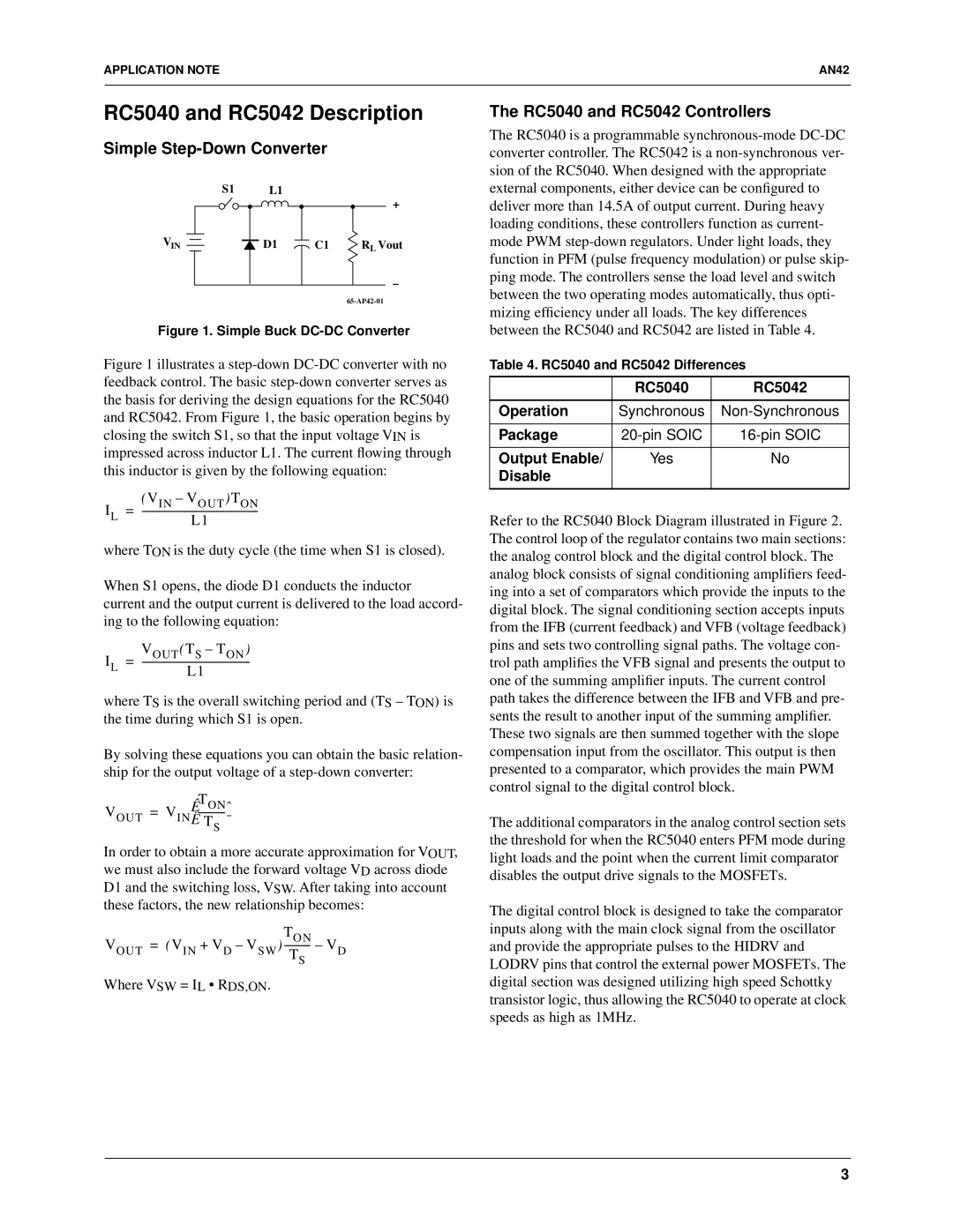
The Fairchild RC5042 and RC5040 are versatile integrated circuits that stand out in the realm of high-performance analog applications. Designed to meet the demands of modern electronic systems, these devices integrate various features and technologies that contribute to their effectiveness in a multitude of applications.The RC5040 is a precision voltage reference that offers a stable, low-noise output, making it ideal for applications such as instrumentation, data acquisition systems, and RF circuits. It boasts an operating temperature range of -40°C to +85°C, ensuring reliability in diverse environments. One of its most significant characteristics is its low-temperature drift, which minimizes variations in output voltage over temperature fluctuations, thereby enhancing the accuracy of devices that utilize it.
On the other hand, the RC5042 is designed as a high-speed comparator with an integrated voltage reference. This dual functionality allows for a more compact design in applications where space is a premium. The RC5042 features an ultra-fast response time and high input impedance, which contribute to its capability to handle rapidly changing signals without distortion. This makes it particularly useful in applications like analog signal processing and threshold detection.
Both devices utilize Fairchild's advanced BiCMOS technology, which combines the benefits of bipolar and CMOS processes. This technology allows the devices to operate with low power consumption while maintaining high speed and operational efficiency. The RC5042 and RC5040 also incorporate noise-reduction techniques, which help in minimizing unwanted disturbances that could impact circuit performance.
Another noteworthy characteristic of both the RC5040 and RC5042 is their ease of integration. They come in compact package sizes, making them easier to incorporate into various designs without compromising on performance. Furthermore, the availability of multiple output options allows engineers the flexibility to choose configurations that best suit their specific applications.
In conclusion, the Fairchild RC5042 and RC5040 are robust devices that offer essential functionality for various high-performance analog applications. With their precision, fast response time, and exceptional reliability, these integrated circuits are a valuable asset in the design of modern electronic systems, catering to the growing demands of the technology landscape.

