Manuals
/
Fedders
/
Household Appliance
/
Air Conditioner
Fedders
Split System Air Conditioner Model, Electrical Connections cont, Braze joints, Evacuation
Models:
Split System Air Conditioner
1
4
8
8
Download
8 pages
61.97 Kb
1
2
3
4
5
6
7
8
Page 4
Image 4
Page 3
Page 5
Page 4
Image 4
Page 3
Page 5
Contents
Installation, Operation and Maintenance
TABLE OF CONTENTS
1.5 Through 5 Ton Split System Air Conditioner
NOTES TO INSTALLER
What You Need To Know About Safety Instructions
INTRODUCTION
CODES
INSTALLATION Condensing Unit Location
Electrical Connections
DANGER
Clearances
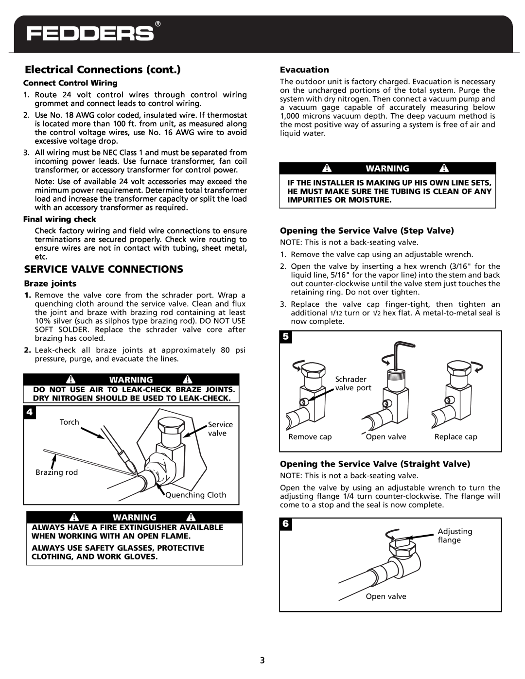
Electrical Connections cont
SERVICE VALVE CONNECTIONS
Opening the Service Valve Step Valve
Opening the Service Valve Straight Valve
Precautions
CONNECT REFRIGERANT PIPING
LIQUID LINE SIZES
SUCTION LINE SIZES
MAINTENANCE INSTRUCTIONS
FINAL CHECKS FOR INSTALLER
SUB-COOLINGCHARGING
OPERATION INSTRUCTIONS
CONDENSING UNIT NOMENCLATURE
C24 A B D 1 V F
Poduct Type
Nominal Capacity
LIMITED WARRANTY
Model C10
REV. 8/06
23-23-0418N-013
Top
Page
Image
Contents