Manuals
/
Fender
/
Home Audio
/
Speaker System
Fender
P/N 051923
owner manual
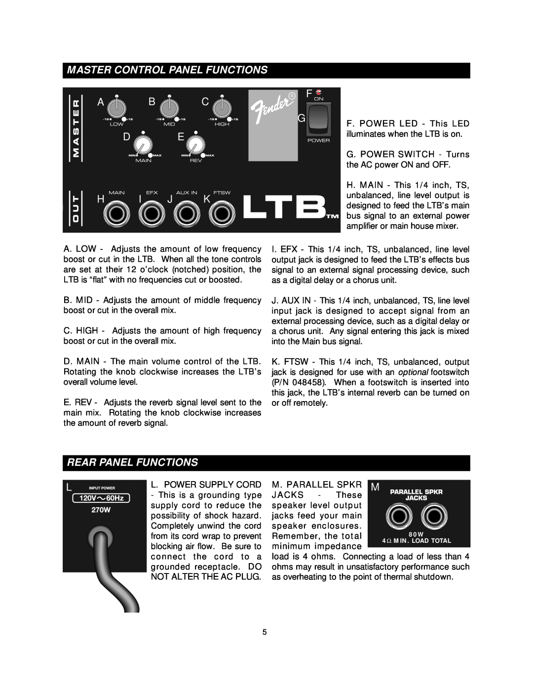
Master Control Panel Functions, Hi Jk, Rear Panel Functions
Models:
P/N 051923
1
5
11
11
Download
11 pages
14.92 Kb
1
2
3
4
5
6
7
8
Troubleshooting
Basic Setup Of Your Ltb
Portable Powered Mixer
Page 5
Image 5
Page 4
Page 6
Page 5
Image 5
Page 4
Page 6
Contents
REV B
PORTABLE SOUND SYSTEMS
From Fender Pro Audio
Fender Musical Instruments
Bill Schultz
THE FENDER LTB
INTRODUCTION
PORTABLE POWERED MIXER
INPUT CHANNEL CONTROL FUNCTIONS
REAR PANEL FUNCTIONS
MASTER CONTROL PANEL FUNCTIONS
HI JK
on the speaker cabinets
BASIC SETUP OF YOUR LTB
VINYL COVERING CARE
TROUBLESHOOTING
GROUNDING AND HUMS
SIMPLE LTB SETUP
RUNNING AN EFFECTS PROCESSOR THRU YOUR LTB
SPECIFICATIONS FOR THE LTB POWERED MIXER
SPECIFICATIONS FOR THE LTB-10SPEAKER ENCLOSURE
Top
Page
Image
Contents