Trimming attachment |
1 Scope of delivery
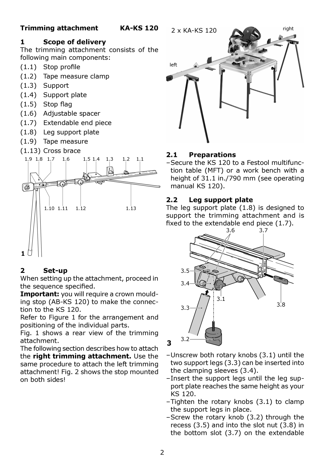
The trimming attachment consists of the following main components:
(1.1) Stop profile
(1.2) Tape measure clamp
(1.3) Support
(1.4) Support plate
(1.5) Stop flag
(1.6) Adjustable spacer
(1.7) Extendable end piece
(1.8) Leg support plate
(1.9) Tape measure
2 x | right |
left
(1.13) Cross brace |
|
|
|
| 2.1 Preparations | ||||
1.9 | 1.8 | 1.7 | 1.6 | 1.5 1.4 | 1.3 | 1.2 | 1.1 | ||
|
|
|
|
|
|
|
| ||
|
|
|
|
|
|
|
| tion table (MFT) or a work bench with a | |
|
|
|
|
|
|
|
| height of 31.1 in./790 mm (see operating | |
|
|
|
|
|
|
|
| manual KS 120). | |
|
| 2.2 Leg support plate |
|
1.10 1.11 1.12 | 1.13 | The leg support plate (1.8) is designed to | |
|
| support the trimming attachment and is | |
|
| fixed to the extendable end piece (1.7). | |
|
| 3.6 | 3.7 |
1
2 |
|
| 3.5 |
|
When setting up the attachment, proceed in |
| 3.4 |
| |
the sequence specified. |
|
| ||
|
|
| ||
Important: you will require a crown mould- |
| 3.1 |
| |
ing stop |
| 3.8 | ||
| 3.3 | |||
tion to the KS 120. |
| |||
|
| |||
Refer to Figure 1 for the arrangement and |
|
|
| |
positioning of the individual parts. |
|
|
| |
Fig. 1 shows a rear view of the trimming |
| 3.2 |
| |
attachment. | 3 |
| ||
The following section describes how to attach |
|
| ||
the right trimming attachment. Use the | ||||
same procedure to attach the left trimming | two support legs (3.3) can be inserted into | |||
attachment! Fig. 2 shows the stop mounted | the clamping sleeves (3.4). |
| ||
on both sides! | ||||
|
| port plate reaches the same height as your | ||
KS 120.
2
