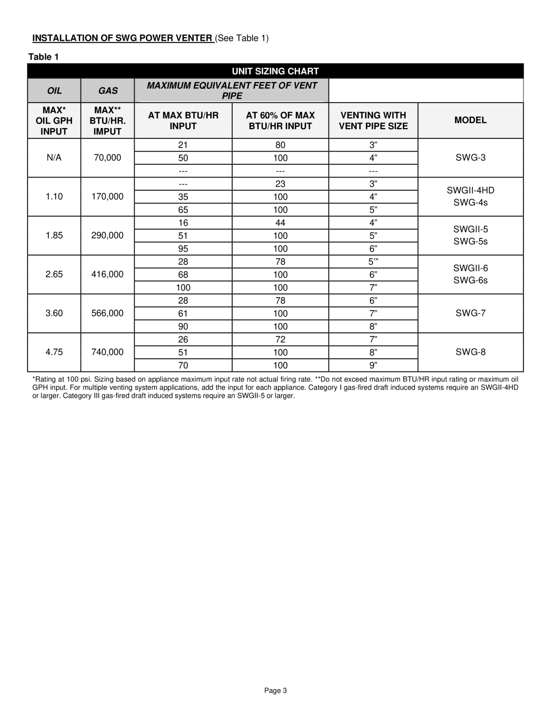
SWGII, SWG, SWG Stainless specifications
Field Controls has established itself as a leader in advanced air quality control solutions, and their SWGII and SWG series, including SWG Stainless, exemplify cutting-edge technology in air purification and ventilation systems. These systems are designed to meet the demanding needs of commercial and residential environments, ensuring optimal air quality and energy efficiency.One of the standout features of the SWGII is its robust design. Built with high-quality stainless steel, this model is resistant to corrosion, making it an excellent choice for applications in areas with high humidity or potential exposure to moisture. The stainless steel construction not only enhances durability but also provides a sleek, professional appearance that suits various installations.
The SWGII utilizes advanced ultraviolet (UV) light technology to eliminate harmful pathogens such as bacteria, mold, and viruses from the air. By integrating UV-C light within the system, it effectively reduces the microbial load, providing a healthier environment without the use of harmful chemicals. This makes it particularly beneficial for hospitals, schools, and other establishments that prioritize cleanliness and hygiene.
In terms of efficiency, the SWG series is engineered to work seamlessly with existing HVAC systems, enhancing air circulation while minimizing energy consumption. The models are equipped with features that allow for variable airflow adjustments, ensuring optimal performance depending on the setting. This adaptability not only improves user comfort but also contributes to significant energy savings over time.
Another notable characteristic of the SWG and SWG Stainless is their user-friendly interface and straightforward installation process. Field Controls has prioritized ease of use, allowing for quick setup and minimal maintenance requirements. This is particularly advantageous for contractors and end-users alike, as it reduces downtime and maintenance costs.
Additionally, the SWG series is designed with environmental considerations in mind. By reducing reliance on traditional methods of air purification and promoting energy efficiency, these systems align with contemporary sustainability practices, making them an ideal choice for eco-conscious consumers and businesses.
In summary, Field Controls SWGII, SWG Stainless, and the broader SWG series represent a significant leap in air quality technology, combining durability, efficiency, and health-focused features into a single system. With their advanced UV technology, robust construction, and user-friendly design, these units are transforming the way we think about indoor air quality. They stand as a testament to Field Controls’ commitment to innovation and their mission to create healthier living and working environments.
