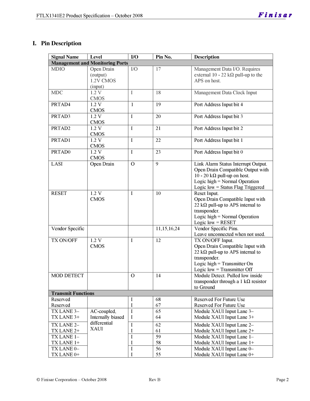
10GBASE-LRM X2, FTLX1341E2 specifications
The Finisar FTLX1341E2 is a robust 10GBASE-LRM X2 transceiver that plays a crucial role in modern optical networking solutions. Designed to facilitate high-speed data transmission, this module is ideal for applications requiring 10 Gigabit Ethernet over multimode fiber (MMF). With its ability to support long-range transmission, the FTLX1341E2 is particularly well-suited for metropolitan area networks and enterprise applications.One of the hallmark features of the FTLX1341E2 is its compliance with the 10GBASE-LRM standard, which ensures compatibility with existing 10 Gigabit Ethernet networks. It operates at wavelengths around 1310 nm and utilizes an innovative process that allows it to transmit over multimode fiber up to 300 meters. This makes it a reliable choice for users looking to maximize the distance of their connections without compromising the performance.
The FTLX1341E2 leverages advanced technologies such as vertical-cavity surface-emitting laser (VCSEL) for efficient light emission, resulting in lower power consumption and enhanced energy efficiency. The module features enhanced optical receiver designs which improve sensitivity, making it ideal for challenging network environments where signal integrity is paramount.
In terms of characteristics, the Finisar FTLX1341E2 supports both the common 850 nm and the longer wavelength 1310 nm optical transceivers, giving it the versatility needed to meet various networking demands. The X2 form factor ensures ease of installation, as it fits seamlessly into standard networking equipment. Furthermore, it boasts advanced digital diagnostics capabilities, enabling real-time monitoring of parameters such as optical power, temperature, and transceiver status.
The FTLX1341E2 is not only compatible with a wide array of network switches and routers but also has been designed to meet stringent industry standards, ensuring quality and reliability. Its plug-and-play functionality allows for quick deployment and integration into existing networks without the need for complex configurations.
In summary, the Finisar FTLX1341E2 10GBASE-LRM X2 transceiver represents a significant innovation in high-speed optical communications. Its combination of long-distance capability, energy efficiency, and compatibility with existing infrastructure makes it an excellent choice for network administrators looking to enhance their data transmission solutions. As businesses continue to evolve and require faster, more reliable connectivity, the FTLX1341E2 is poised to meet those needs effectively.
