F i n i s a r |
I.SFP to Host Connector Pin Out
Pin | Symbol | Name/Description | Note |
1 | VEET | Transmitter ground (common with receiver ground) | 1 |
2 | TFAULT | Transmitter Fault. Not supported |
|
3 | TDIS | Transmitter Disable. PHY disabled on high or open | 2 |
4 | MOD_DEF(2) | Module Definition 2. Data line for serial ID | 3 |
5 | MOD_DEF(1) | Module Definition 1. Clock line for serial ID | 3 |
6 | MOD_DEF(0) | Module Definition 0. Grounded within the module | 3 |
7 | Rate Select | No connection required |
|
8 | LOS | Loss of Signal indication. | 4 |
9 | VEER | Receiver ground (common with transmitter ground) | 1 |
10 | VEER | Receiver ground (common with transmitter ground) | 1 |
11 | VEER | Receiver ground (common with transmitter ground) | 1 |
12 | RD- | Receiver Inverted DATA out. AC coupled |
|
13 | RD+ | Receiver |
|
14 | VEER | Receiver ground (common with transmitter ground) | 1 |
15 | VCCR | Receiver power supply |
|
16 | VCCT | Transmitter power supply |
|
17 | VEET | Transmitter ground (common with receiver ground) | 1 |
18 | TD+ | Transmitter |
|
19 | TD- | Transmitter Inverted DATA in. AC coupled |
|
20 | VEET | Transmitter ground (common with receiver ground) | 1 |
Notes: | 1. Circuit ground is | connected to chassis ground |
|
2.PHY disabled on TDIS > 2.0V or open, enabled on TDIS < 0.8V
3.Should be pulled up with 4.7k – 10k Ohms on host board to a voltage between 2.0 V and 3.6 V.
MOD_DEF(0) pulls line low to indicate module is plugged in.
4.LVTTL compatible with a maximum voltage of 2.5V. Not supported on
Table 1. SFP to host connector pin assignments and descriptions
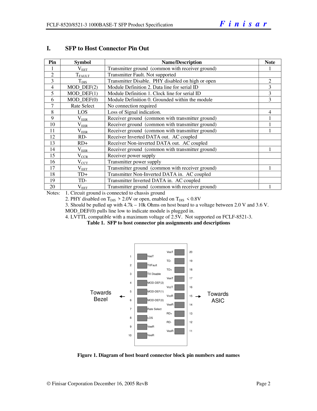
Towards
Bezel
1
2
3
4
5
6
7
8
9
10
VeeT
VeeT
TD-
TXFault
TD+
TX Disable
VeeT
VccT
VccR
VeeR
Rate Select
RD+
LOS
RD-
VeeR
VeeR
![]()
![]() VeeR
VeeR
20
19
18
17
16
15
14
13
12
11
Towards
ASIC
Figure 1. Diagram of host board connector block pin numbers and names
♥ Finisar Corporation December 16, 2005 RevB | Page 2 |