FTLX8561E2 specifications
The Finisar FTLX8561E2 is a high-performance optical transceiver designed for Data Center and enterprise networking applications. This device operates over multimode fiber and is compliant with relevant industry standards, making it a preferred choice for high-bandwidth data transmission.One of the standout features of the FTLX8561E2 is its support for 10 Gigabit Ethernet (10GbE) applications. It complies with the IEEE 802.3ae standard, which guarantees reliable performance for Ethernet systems. The transceiver is optimized for use in short-range applications, enabling data transmission over distances up to 300 meters when using OM3 multimode fiber and up to 400 meters with OM4 multimode fiber. This flexibility makes it ideal for installations within data centers where high-speed connectivity is crucial.
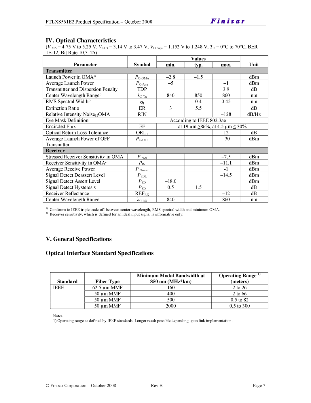
The FTLX8561E2 operates at a nominal wavelength of 850 nm, offering improved performance and increased transmission efficiency. It employs advanced vertical-cavity surface-emitting laser (VCSEL) technology to produce a high-quality optical signal, ensuring minimal signal degradation over short distances. This technology is particularly important for maintaining signal integrity in high-density environments.
In terms of form factor, the FTLX8561E2 is designed in a SFP+ (Small Form-factor Pluggable) form factor, making it easy to install and replace in various networking devices. This compact size allows for higher port density on switches and routers, which is essential for modern data centers that prioritize space efficiency.
The transceiver delivers a maximum bit rate of 10 Gbps, making it suitable for bandwidth-intensive applications. Additionally, it features low power consumption, with typical power usage around 1.5 watts, contributing to energy-efficient networking solutions.
In terms of compatibility, the FTLX8561E2 can be used with a variety of switch and router brands, ensuring versatility across different systems. Its reliability is backed by rigorous testing and compliance with MSA (Multi-Source Agreement) standards.
In summary, the Finisar FTLX8561E2 is an ideal choice for professionals seeking an efficient and reliable 10GbE solution. With its advanced technologies, including VCSEL, multimode fiber compatibility, and energy-efficient design, it enhances network performance in both enterprise and data center environments.