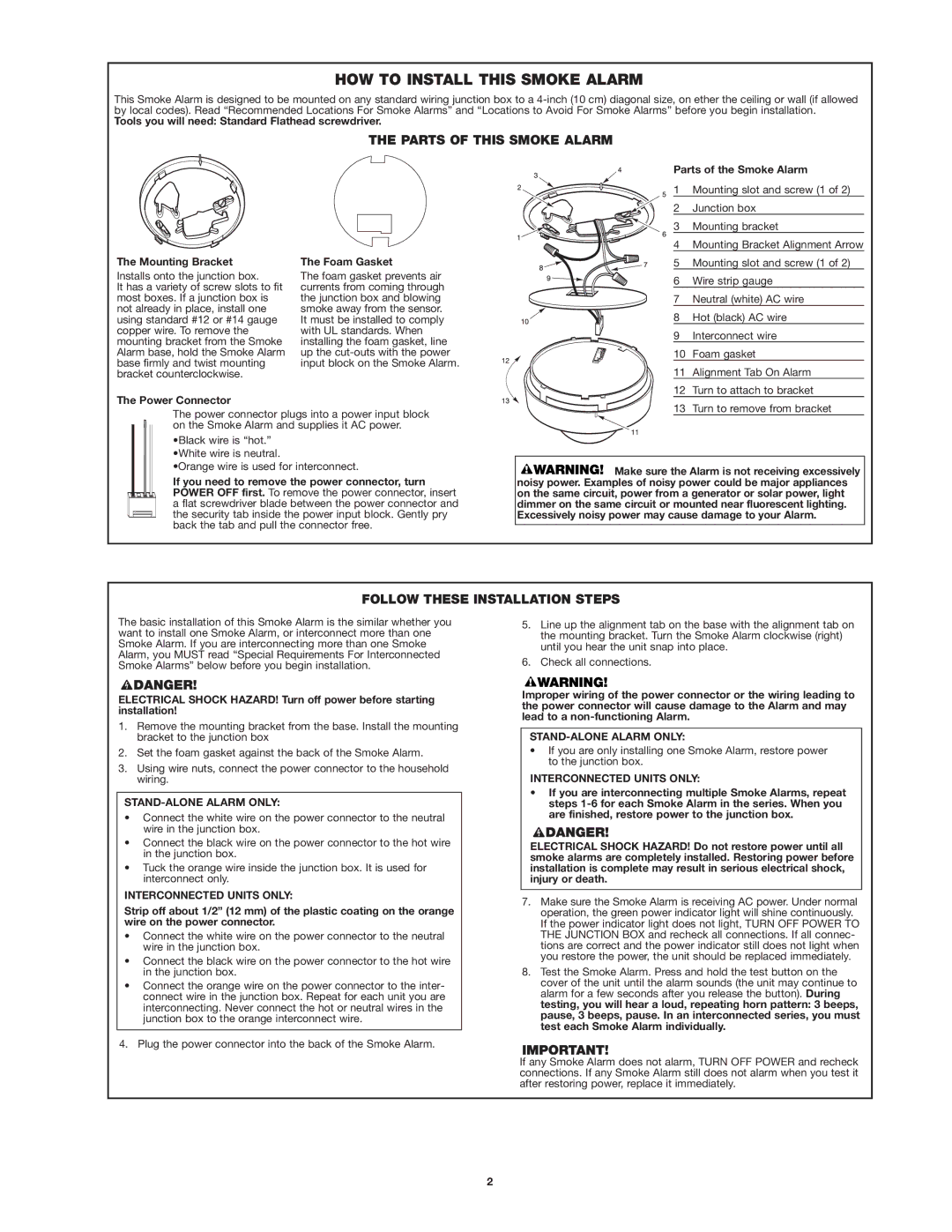
HOW TO INSTALL THIS SMOKE ALARM

This Smoke Alarm is designed to be mounted on any standard wiring junction box to a 4-inch (10 cm) diagonal size, on ether the ceiling or wall (if allowed by local codes). Read “Recommended Locations For Smoke Alarms” and “Locations to Avoid For Smoke Alarms” before you begin installation.

Tools you will need: Standard Flathead screwdriver.

THE PARTS OF THIS SMOKE ALARM

The Mounting Bracket

Installs onto the junction box.

It has a variety of screw slots to fit most boxes. If a junction box is not already in place, install one using standard #12 or #14 gauge copper wire. To remove the mounting bracket from the Smoke Alarm base, hold the Smoke Alarm base firmly and twist mounting bracket counterclockwise.

The Power Connector

The Foam Gasket

The foam gasket prevents air currents from coming through the junction box and blowing smoke away from the sensor. It must be installed to comply with UL standards. When installing the foam gasket, line up the cut-outs with the power input block on the Smoke Alarm.

Parts of the Smoke Alarm

1 Mounting slot and screw (1 of 2)

2 Junction box

3 Mounting bracket

4 Mounting Bracket Alignment Arrow

5 Mounting slot and screw (1 of 2)

6 Wire strip gauge

7 Neutral (white) AC wire

8 Hot (black) AC wire

9 Interconnect wire

10 Foam gasket

11 Alignment Tab On Alarm

12 Turn to attach to bracket

The power connector plugs into a power input block on the Smoke Alarm and supplies it AC power.

•Black wire is “hot.” •White wire is neutral.

•Orange wire is used for interconnect.

If you need to remove the power connector, turn POWER OFF first. To remove the power connector, insert a flat screwdriver blade between the power connector and the security tab inside the power input block. Gently pry back the tab and pull the connector free.

13 Turn to remove from bracket

Make sure the Alarm is not receiving excessively noisy power. Examples of noisy power could be major appliances on the same circuit, power from a generator or solar power, light dimmer on the same circuit or mounted near fluorescent lighting. Excessively noisy power may cause damage to your Alarm.

FOLLOW THESE INSTALLATION STEPS

The basic installation of this Smoke Alarm is the similar whether you want to install one Smoke Alarm, or interconnect more than one Smoke Alarm. If you are interconnecting more than one Smoke Alarm, you MUST read “Special Requirements For Interconnected Smoke Alarms” below before you begin installation.

ELECTRICAL SHOCK HAZARD! Turn off power before starting installation!

1.Remove the mounting bracket from the base. Install the mounting bracket to the junction box

2.Set the foam gasket against the back of the Smoke Alarm.

3.Using wire nuts, connect the power connector to the household wiring.

STAND-ALONE ALARM ONLY:

Connect the white wire on the power connector to the neutral wire in the junction box.

Connect the black wire on the power connector to the hot wire in the junction box.

Tuck the orange wire inside the junction box. It is used for interconnect only.

INTERCONNECTED UNITS ONLY:

Strip off about 1/2” (12 mm) of the plastic coating on the orange wire on the power connector.

Connect the white wire on the power connector to the neutral wire in the junction box.

Connect the black wire on the power connector to the hot wire in the junction box.

Connect the orange wire on the power connector to the inter- connect wire in the junction box. Repeat for each unit you are interconnecting. Never connect the hot or neutral wires in the junction box to the orange interconnect wire.

4.Plug the power connector into the back of the Smoke Alarm.

5.Line up the alignment tab on the base with the alignment tab on the mounting bracket. Turn the Smoke Alarm clockwise (right) until you hear the unit snap into place.

6.Check all connections.

Improper wiring of the power connector or the wiring leading to the power connector will cause damage to the Alarm and may lead to a non-functioning Alarm.

STAND-ALONE ALARM ONLY:

If you are only installing one Smoke Alarm, restore power to the junction box.

INTERCONNECTED UNITS ONLY:

If you are interconnecting multiple Smoke Alarms, repeat steps 1-6 for each Smoke Alarm in the series. When you are finished, restore power to the junction box.

ELECTRICAL SHOCK HAZARD! Do not restore power until all smoke alarms are completely installed. Restoring power before installation is complete may result in serious electrical shock, injury or death.

7.Make sure the Smoke Alarm is receiving AC power. Under normal operation, the green power indicator light will shine continuously. If the power indicator light does not light, TURN OFF POWER TO THE JUNCTION BOX and recheck all connections. If all connec- tions are correct and the power indicator still does not light when you restore the power, the unit should be replaced immediately.

8.Test the Smoke Alarm. Press and hold the test button on the cover of the unit until the alarm sounds (the unit may continue to alarm for a few seconds after you release the button). During testing, you will hear a loud, repeating horn pattern: 3 beeps, pause, 3 beeps, pause. In an interconnected series, you must test each Smoke Alarm individually.

If any Smoke Alarm does not alarm, TURN OFF POWER and recheck connections. If any Smoke Alarm still does not alarm when you test it after restoring power, replace it immediately.

2

Page 2
Image 2
First Alert SA100B, 100S HOW to Install this Smoke Alarm, Parts of this Smoke Alarm, Follow These Installation Steps

100S, SA100B specifications

The First Alert 100S and SA100B smoke alarms are integral components of modern home safety systems, designed to keep families safe from the dangers of fire. Both models boast a range of advanced features that enhance their performance and reliability in detecting smoke and alerting occupants.

One of the standout characteristics of the First Alert 100S is its ionization sensing technology. This technology is particularly effective at detecting fast-flaming fires, which can arise from burning paper, wood, and other common household materials. Ionization smoke alarms work by using a small amount of radioactive material to ionize air in the sensing chamber, creating a current. When smoke enters the chamber, it disrupts this current, triggering the alarm. This feature makes the 100S an ideal choice for those seeking prompt response to sudden fire outbreaks.

On the other hand, the SA100B employs a photoelectric sensing technology. Unlike ionization alarms, photoelectric models are adept at detecting smoldering fires that produce larger smoke particles. By utilizing a light source and a light sensor, the SA100B can sense when smoke enters the light beam, activating the alarm. This dual-sensing capability in some models helps to ensure optimal detection of various fire types, reducing the risk of false alarms while maximizing safety.

Both models come with several user-friendly features designed to enhance usability. They include a loud 85-decibel alarm to ensure that the sound penetrates through the ambient noise in a household, alerting everyone to the danger present. Additionally, the battery backup ensures continuous operation during power outages, which is crucial in emergencies.

Installation and maintenance are also simplified in these devices. The First Alert models are typically easy to mount on ceilings or walls, and most models feature a test button, allowing users to quickly verify that the alarm is functioning correctly. The low battery indicator signals when it's time to replace the battery, further decreasing the risk of device failure.

In conclusion, the First Alert 100S and SA100B smoke alarms are dependable choice for fire safety, combining advanced technologies with user-friendly features. Their specific sensing capabilities ensure they provide comprehensive protection against different types of fires, making them essential for every household's safety plan.