FS 520, FS 513, FS 524 specifications
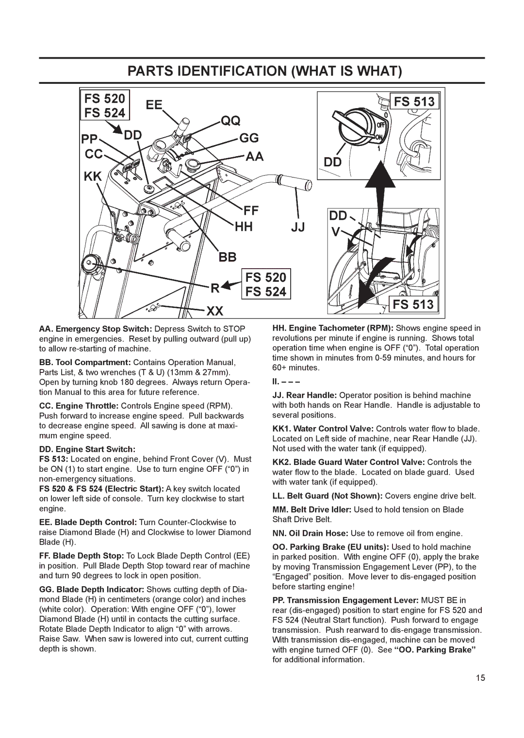
Husqvarna, a renowned name in outdoor power equipment, offers a robust range of walk-behind floor saws designed for professionals and contractors. Among their offerings, the FS 524, FS 513, and FS 520 stand out as exceptional choices, each possessing unique features and technologies that cater to a variety of concrete cutting needs.The Husqvarna FS 524 is designed for medium-sized jobs and is known for its efficiency and user-friendliness. This model features a powerful engine that delivers consistent performance while minimizing fuel consumption. The FS 524 is equipped with a hand-lever locking for cutting depth, ensuring precision during operation. Its unique design allows for easy transportation and setup, making it ideal for contractors who move between job sites frequently. Moreover, its foldable handlebars enhance compact storage, further improving mobility.
Next in line, the FS 513 is recognized for its compact design and versatility. Engineered for homeowners and small businesses, the FS 513 features a lightweight yet durable construction that doesn't sacrifice performance. With an adjustable depth control and quick-release blade guard, operators can easily change blades and adjust depths without extensive downtime. The robust engine ensures ample power while the vibration-dampening system provides a comfortable experience, reducing operator fatigue over long periods of use.
The FS 520 is a yet more powerful option, suited for larger projects requiring enhanced cutting depth and efficiency. It features the advanced SmartGuard technology, which enhances safety by automatically adjusting the cutting depth based on the blade utilized. The high-performance engine partnered with premium blades allows for deep cuts and efficient material removal, ideal for roadwork and large-scale repairs. The FS 520 also includes a user-friendly control panel that provides easy access to essential functions, ensuring an optimal cutting experience.
All three models utilize Husqvarna’s proprietary technologies, including their state-of-the-art blade cooling system that reduces wear and increases blade life. The ergonomic designs across the FS series help improve operator comfort and control, making these saws suitable for extended periods of use. In summary, the Husqvarna FS 524, FS 513, and FS 520 offer unmatched reliability, performance, and advanced features that empower professionals to tackle concrete cutting projects with confidence and precision.

