HOW TO INSTALL THIS ALARM
For quick installation instructions see the “Quick and Easy Guide to Programming Your ONELINK® Alarm and Using the Optional Features”.
This combination Smoke/CO Alarm was designed to be mounted on the ceiling or wall. It is not a tabletop device. You must install this device on the ceiling or wall as outlined below. Read “Where To Install This Alarm” before starting.
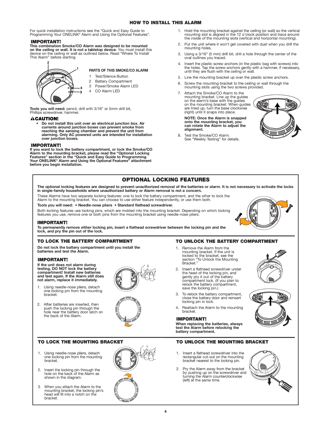
PARTS OF THIS SMOKE/CO ALARM
1 Test/Silence Button
2 Battery Compartment
3 Power/Smoke Alarm LED
4 CO Alarm LED
Tools you will need: pencil, drill with 3/16” or 5mm drill bit, Phillips screwdriver, hammer.
•Do not install this unit over an electrical junction box. Air currents around junction boxes can prevent smoke from reaching the sensing chamber and prevent the unit from alarming. Only AC powered units are intended for installation over junction boxes.
If you want to lock the battery compartment, or lock the Smoke/CO Alarm to the mounting bracket, please read the “Optional Locking Features” section in the “Quick and Easy Guide to Programming Your ONELINK® Alarm and Using the Optional Features” attachment before you begin installation.
1.Hold the mounting bracket against the ceiling (or wall) so the vertical mounting slot is aligned in the 12 o’clock position and trace around the inside of the mounting slots (vertical and horizontal mounting).
2.Put the unit where it won’t get covered with dust when you drill the mounting holes.
3.Using a 3/16” (5 mm) drill bit, drill a hole through the center of the oval outlines you traced.
4.Insert the plastic screw anchors (in the plastic bag with screws) into the holes. Tap the screw anchors gently with a hammer, if necessary, until they are flush with the ceiling or wall.
5.Line the mounting bracket up over the plastic screw anchors.
6.Screw the mounting bracket to the ceiling or wall through the mounting slots using the two screws provided.
7.Attach the Smoke/CO Alarm to the mounting bracket. Line up the guides
on the alarm’s base with the guides on the mounting bracket. When guides are lined up, turn the base clockwise (right) until it snaps into place.
NOTE: Once the Alarm is snapped onto the mounting bracket, you can rotate the Alarm to adjust the alignment.
8. Test the Smoke/CO Alarm.
See “Weekly Testing” for details.
OPTIONAL LOCKING FEATURES
The optional locking features are designed to prevent unauthorized removal of the batteries or alarm. It is not necessary to activate the locks in
These Alarms have two separate locking features: one to lock the battery compartment, and the other to lock the Alarm to the mounting bracket. You can choose to use either feature independently, or use them both.
Tools you will need: •
Both locking features use locking pins, which are molded into the mounting bracket. Depending on which locking features you use, remove one or both pins from the mounting bracket using
To permanently remove either locking pin, insert a flathead screwdriver between the locking pin and the lock, and pry the pin out of the lock.
TO LOCK THE BATTERY COMPARTMENT
Do not lock the battery compartment until you install the batteries and test the Alarm.
If the unit does not alarm during testing, DO NOT lock the battery compartment! Install new batteries and test again. If the Alarm still does not alarm, replace it immediately.
1. Using
2. After batteries are inserted, then push the locking pin through the hole near the battery door latch on the back of the Alarm.
TO UNLOCK THE BATTERY COMPARTMENT
1. Remove the Alarm from the mounting bracket. If the unit is locked to the bracket, see the section “To Unlock the Mounting Bracket.”
2. Insert a flathead screwdriver under the head of the locking pin, and gently pry it out of the battery compartment lock. (If you plan to relock the battery compartment, save the locking pin.)
3. To relock the battery compartment, close the battery door and reinsert locking pin in lock.
4. Reattach the Alarm to the mounting bracket.
When replacing the batteries, always test the Alarm before relocking the battery compartment.
TO LOCK THE MOUNTING BRACKET
1. Using
2. Insert the locking pin through the hole on the back of the Alarm as shown in the diagram.
3. When you attach the Alarm to the mounting bracket, the locking pin’s head will fit into a notch on the bracket.
TO UNLOCK THE MOUNTING BRACKET
1. Insert a flathead screwdriver into the rectangular
2. Pry the Alarm away from the bracket by pushing up on the screwdriver and turning the Alarm counterclockwise (left) at the same time.
4