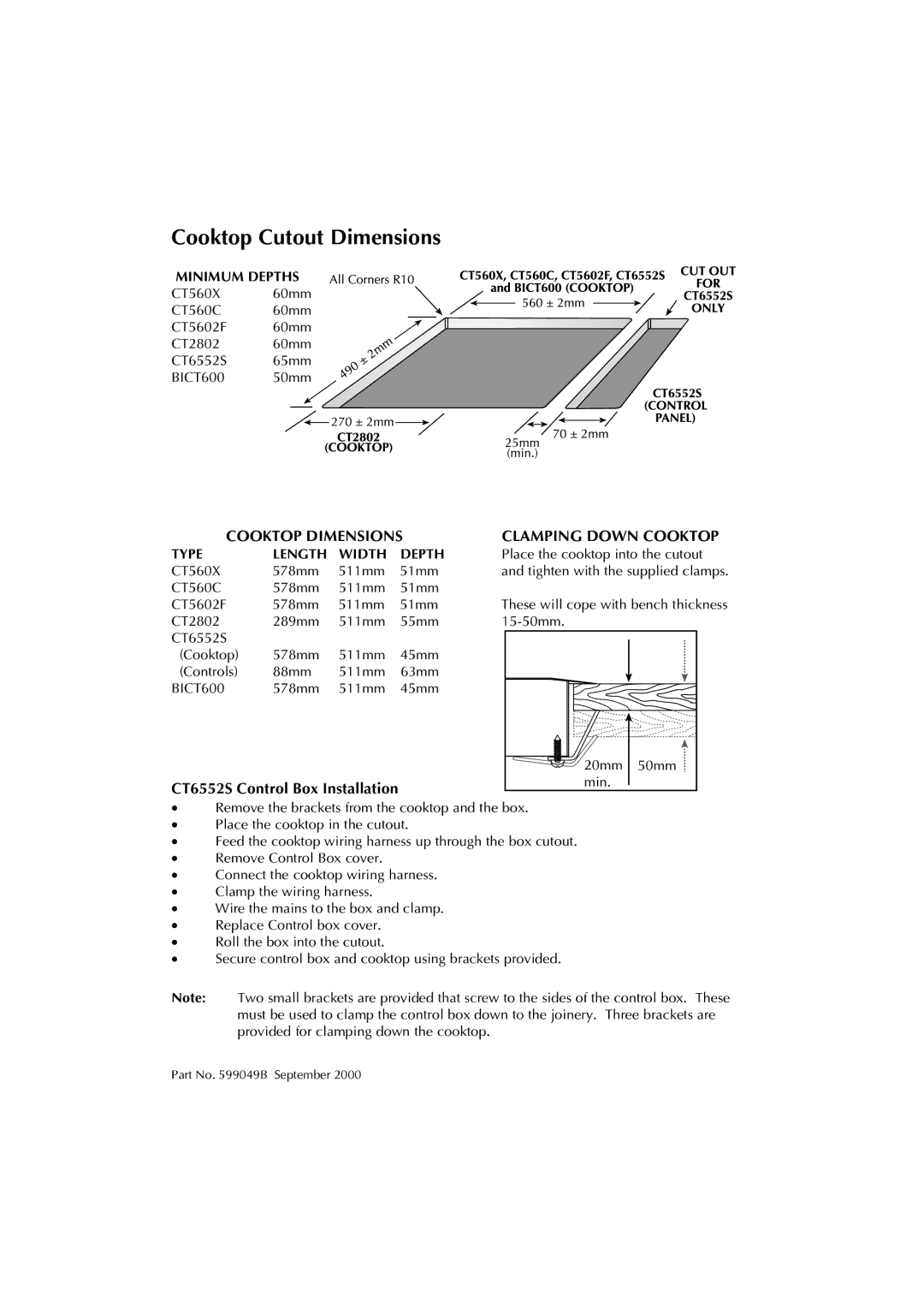
Cooktop Cutout Dimensions
MINIMUM DEPTHS
CT560X 60mm
CT560C 60mm
CT5602F 60mm
CT2802 60mm
CT6552S 65mm
BICT600 50mm
COOKTOP DIMENSIONS
TYPE | LENGTH | WIDTH | DEPTH |
CT560X | 578mm | 511mm | 51mm |
CT560C | 578mm | 511mm | 51mm |
CT5602F | 578mm | 511mm | 51mm |
CT2802 | 289mm | 511mm | 55mm |
CT6552S |
|
|
|
(Cooktop) | 578mm | 511mm | 45mm |
(Controls) | 88mm | 511mm | 63mm |
BICT600 | 578mm | 511mm | 45mm |
CT6552S Control Box Installation
CLAMPING DOWN COOKTOP
Place the cooktop into the cutout and tighten with the supplied clamps.
These will cope with bench thickness
20mm | 50mm |
min. |
|
·Remove the brackets from the cooktop and the box.
·Place the cooktop in the cutout.
·Feed the cooktop wiring harness up through the box cutout.
·Remove Control Box cover.
·Connect the cooktop wiring harness.
·Clamp the wiring harness.
·Wire the mains to the box and clamp.
·Replace Control box cover.
·Roll the box into the cutout.
·Secure control box and cooktop using brackets provided.
Note: Two small brackets are provided that screw to the sides of the control box. These must be used to clamp the control box down to the joinery. Three brackets are provided for clamping down the cooktop.
Part No. 599049B September 2000
