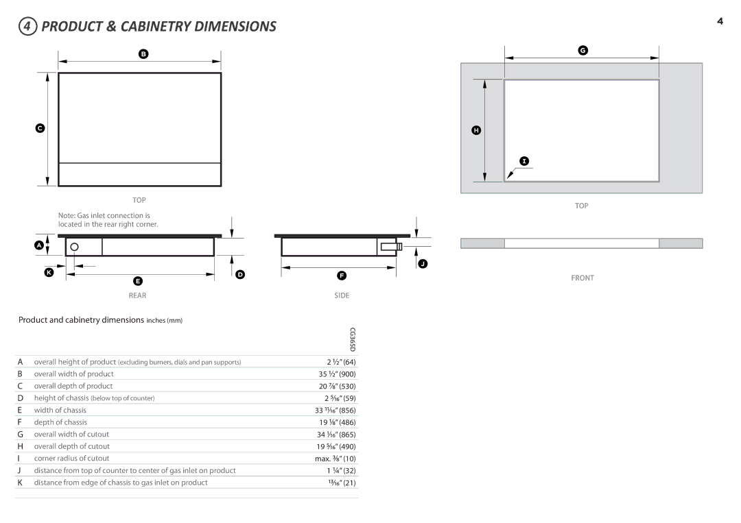
CG365D specifications
The Fisher & Paykel CG365D is a premier gas cooktop that embodies innovation and precision in culinary design. With its sleek and modern aesthetic, it seamlessly fits into any contemporary kitchen while offering exceptional performance. This cooktop is a popular choice among home chefs who value both functionality and style.One of the key features of the CG365D is its robust design, which includes five burners crafted from high-grade stainless steel. This material not only enhances durability but also provides an easy-to-clean surface that maintains its shine over time. The cooktop is available in a classic stainless steel finish, adding a touch of elegance to your kitchen space.
The burners offer a range of power outputs, catering to various cooking needs. The dual flame wok burner is a standout feature, capable of delivering intense heat while offering precise control. This makes it ideal for stir-frying, deep-frying, and quickly boiling water, ensuring your meals are cooked to perfection every time.
Equipped with intuitive dial controls, the CG365D allows for effortless adjustments to heat levels. Each burner features a unique flame-failure safety device, ensuring a safe cooking experience by automatically shutting off the gas supply if the flame goes out. This safety feature provides peace of mind, especially in bustling kitchen environments.
Another remarkable technology integrated into this cooktop is the easy-to-remove, dishwasher-safe trivets. These cast iron components are designed to provide excellent heat retention while ensuring that you can easily clean and maintain the cooking surface. Additionally, the cooktop's design includes a continuous surface that allows for seamless movement of pots and pans from burner to burner.
The Fisher & Paykel CG365D also features a minimalist design with hidden controls, which reduces clutter and enhances the overall look of your kitchen. The precision cooking allows for better heat distribution, promoting even cooking regardless of the dish you’re preparing.
In summary, the Fisher & Paykel CG365D gas cooktop is built for those who appreciate quality, safety, and style. With its powerful burners, innovative technologies, and elegant design, it stands out as a premier choice for modern kitchens. This cooktop not only meets the demands of serious chefs but also elevates the culinary experience with its user-friendly features and thoughtful design. Whether you are simmering sauces or searing meats, the CG365D ensures that you can cook with confidence and finesse.

