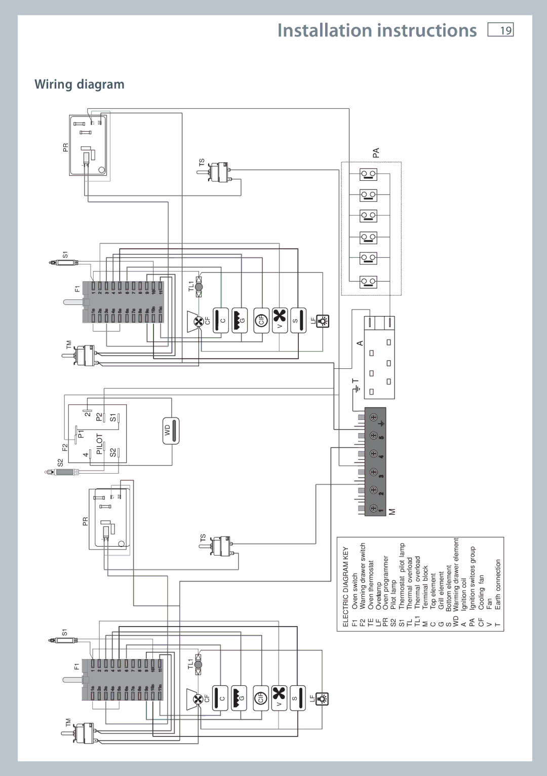
OR120 specifications
Fisher & Paykel OR120 is a versatile and high-performance range cooker designed to meet the culinary needs of both home chefs and professionals. Boasting a combination of innovative technologies and thoughtful design, the OR120 delivers exceptional cooking flexibility and efficiency, allowing users to create a variety of dishes seamlessly.One of the standout features of the OR120 is its dual fuel configuration. This system combines the responsive heat of gas burners with the even and controlled cooking of an electric oven. This dual fuel setup offers enhanced cooking precision, ensuring that users can achieve the best results for diverse cooking techniques, from rapid boiling to slow roasting.
The OR120 features a spacious oven compartment with a generous capacity, making it ideal for preparing large meals or multiple dishes simultaneously. Equipped with multiple cooking functions, including bake, broil, and convection, the oven ensures even heat distribution for consistent cooking results. The convection feature is particularly useful, as it circulates hot air around the oven, reducing cooking times and enhancing flavor development.
For ease of usability, the OR120 comes equipped with intuitive controls and a large digital display. This user-friendly interface allows for precise temperature adjustments and cooking time settings, providing users complete control over their culinary creations. Additionally, the integrated timers and cooking progress indicators enhance the cooking experience, providing convenience and assurance.
Aesthetic appeal is another hallmark of the OR120. Its sleek design, available in a range of finishes, such as stainless steel and classic white, ensures that it complements any kitchen décor. The high-quality materials used in its construction not only enhance its durability but also make it easy to clean.
Safety is a priority in the OR120 design, with features such as flame failure protection and a cooling fan to prevent overheating. This ensures peace of mind while cooking, allowing users to focus on the task at hand.
In summary, Fisher & Paykel’s OR120 stands out as a premium choice for those seeking a combination of performance, versatility, and style in a range cooker. With features designed to enhance cooking efficiency and ease of use, it’s a valuable asset for any kitchen. Whether for everyday meals or special occasions, the OR120 can elevate the cooking experience, allowing users to explore their culinary passions with confidence.

