433, 434 specifications
The Fluke 434 and 433 are advanced power quality analyzers designed for electrical engineers and technicians who require comprehensive data on power usage and quality in electrical systems. These instruments help diagnose energy issues, improve efficiency, and ensure compliance with various standards.One of the standout features of the Fluke 434 and 433 is their ability to measure a wide range of electrical parameters. Both models offer measurements of voltage, current, power, energy, and power factor across three-phase systems. In addition to these basic functions, they also provide advanced analysis of harmonic distortion, which is crucial for maintaining the reliability and efficiency of electrical equipment.
Another key technology integrated into the Fluke 434 and 433 is the real-time analysis feature. Users can view data in real-time, enabling immediate diagnosis and troubleshooting of issues. The large graphical display further enhances user experience by presenting data in a clear and easily understandable format. Data logging capabilities are robust, allowing for the collection of extensive information over time. Users can store and analyze trends, aiding in long-term decision-making and planning for necessary electrical maintenance or upgrades.
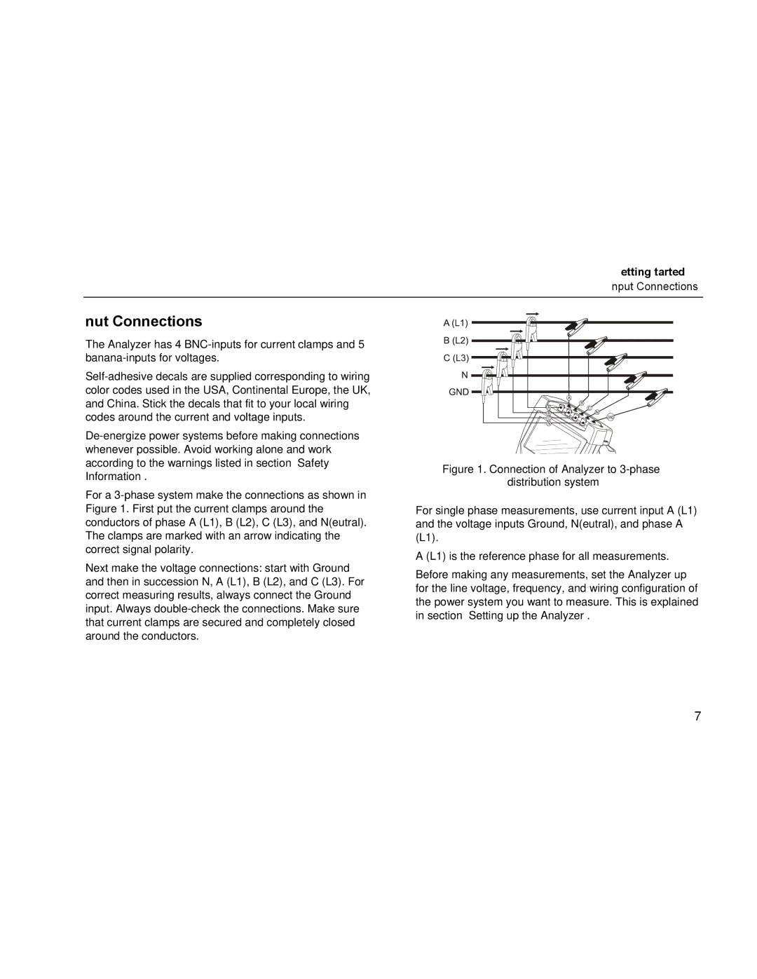
The connection options for the Fluke 434 and 433 are designed with convenience in mind, featuring both wired and wireless capabilities. This flexibility allows users to remotely monitor and manage the analyzers, which is especially useful in large or complex electrical systems. Additionally, these devices are equipped with a variety of input options, including current clamps and voltage probes, making them versatile tools for different applications.
Safety is paramount in electrical work, and both models come with several protective features. They are designed to meet international safety standards, ensuring reliable operation in high-voltage environments. The robust build quality further enhances durability, making them suitable for use in demanding industrial settings.
Overall, the Fluke 434 and 433 power quality analyzers combine sophisticated measurement capabilities with user-friendly interfaces and robust connectivity. Their ability to monitor a variety of parameters makes them essential tools for anyone tasked with maintaining electrical systems and improving energy efficiency in both commercial and industrial settings.

