D4 |
D5 |
D6
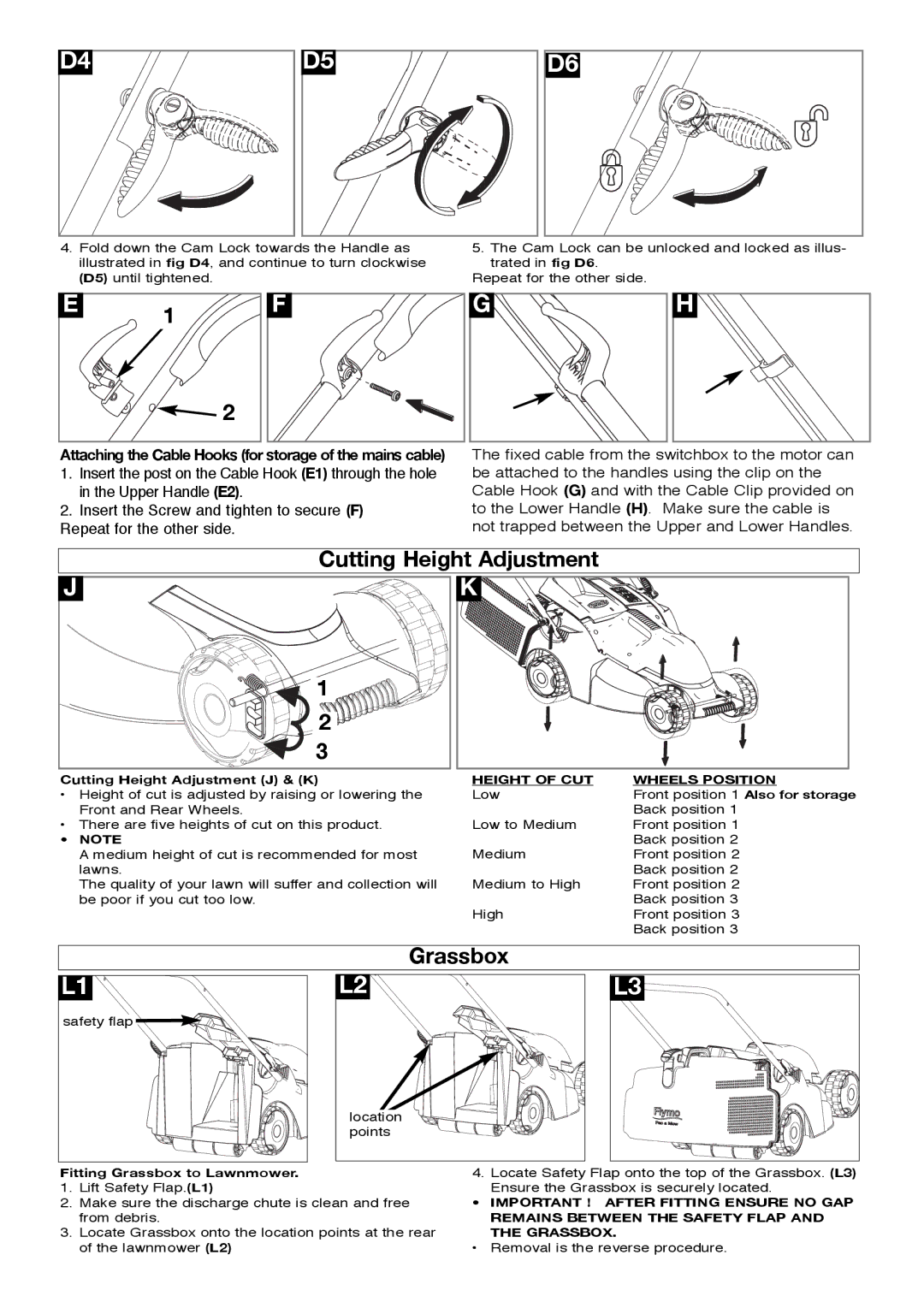
4.Fold down the Cam Lock towards the Handle as illustrated in fig D4, and continue to turn clockwise (D5) until tightened.
5.The Cam Lock can be unlocked and locked as illus- trated in fig D6.
Repeat for the other side.
E | 1 |
| |
| 2 |
F |
G |
H |
Attaching the Cable Hooks (for storage of the mains cable)
1.Insert the post on the Cable Hook (E1) through the hole in the Upper Handle (E2).
2.Insert the Screw and tighten to secure (F)
Repeat for the other side.
The fixed cable from the switchbox to the motor can be attached to the handles using the clip on the Cable Hook (G) and with the Cable Clip provided on to the Lower Handle (H). Make sure the cable is not trapped between the Upper and Lower Handles.
|
| Cutting Height Adjustment |
| |
J |
|
| K |
|
|
| 1 |
|
|
|
| 2 |
|
|
|
| 3 |
|
|
Cutting Height Adjustment (J) & (K) | HEIGHT OF CUT | WHEELS POSITION | ||
• | Height of cut is adjusted by raising or lowering the | Low | Front position 1 Also for storage | |
| Front and Rear Wheels. |
|
| Back position 1 |
• | There are five heights of cut on this product. | Low to Medium | Front position 1 | |
• | NOTE |
|
| Back position 2 |
| A medium height of cut is recommended for most | Medium | Front position 2 | |
| lawns. |
|
| Back position 2 |
| The quality of your lawn will suffer and collection will | Medium to High | Front position 2 | |
| be poor if you cut too low. |
|
| Back position 3 |
|
|
| High | Front position 3 |
|
|
|
| Back position 3 |
|
| Grassbox |
| |
L1 | L2 |
| L3 | |
safety flap |
|
|
| |
|
| location |
|
|
|
| points |
|
|
Fitting Grassbox to Lawnmower.
1.Lift Safety Flap.(L1)
2.Make sure the discharge chute is clean and free from debris.
3.Locate Grassbox onto the location points at the rear of the lawnmower (L2)
4. Locate Safety Flap onto the top of the Grassbox. (L3) Ensure the Grassbox is securely located.
•IMPORTANT ! AFTER FITTING ENSURE NO GAP REMAINS BETWEEN THE SAFETY FLAP AND THE GRASSBOX.
•Removal is the reverse procedure.