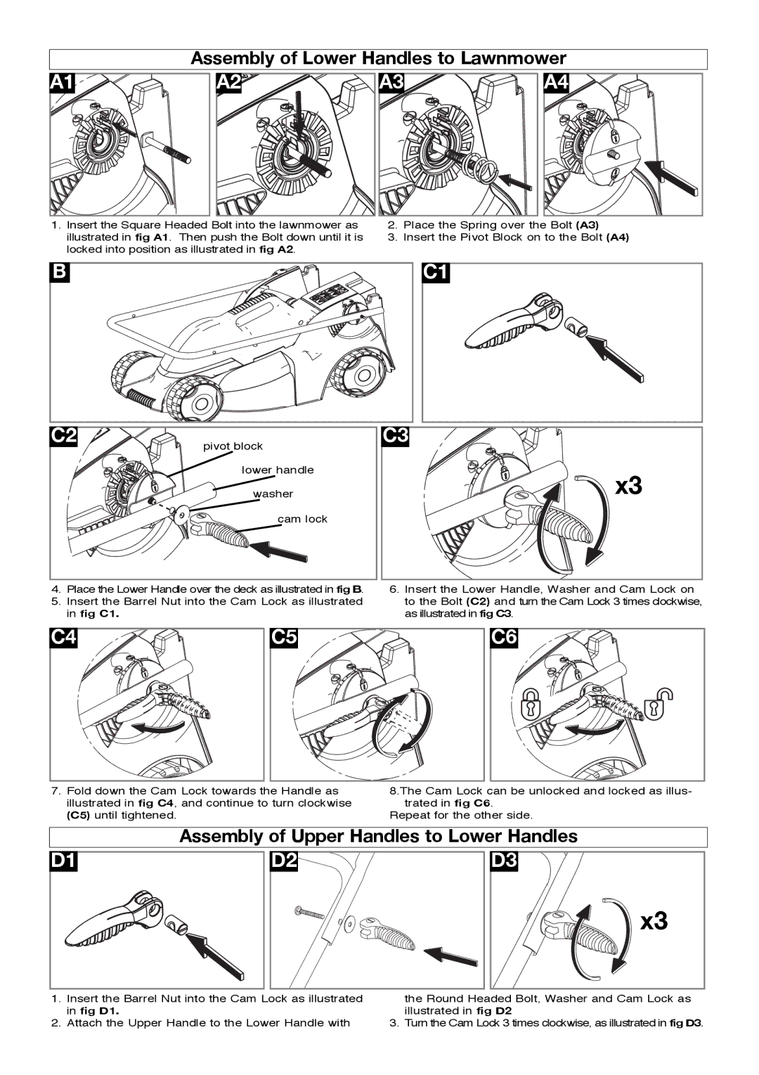
Assembly of Lower Handles to Lawnmower
A1 |
A2 |
A3 |
A4 |
1.Insert the Square Headed Bolt into the lawnmower as illustrated in fig A1. Then push the Bolt down until it is locked into position as illustrated in fig A2.
2.Place the Spring over the Bolt (A3)
3.Insert the Pivot Block on to the Bolt (A4)
B
C2
pivot block
lower handle
washer
cam lock
C3
C1 |
x3 |
4.Place the Lower Handle over the deck as illustrated in fig B.
5.Insert the Barrel Nut into the Cam Lock as illustrated in fig C1.
6.Insert the Lower Handle, Washer and Cam Lock on to the Bolt (C2) and turn the Cam Lock 3 times clockwise, as illustrated in fig C3.
C4 |
C5 |
C6 |
7.Fold down the Cam Lock towards the Handle as illustrated in fig C4, and continue to turn clockwise (C5) until tightened.
8.The Cam Lock can be unlocked and locked as illus- trated in fig C6.
Repeat for the other side.
Assembly of Upper Handles to Lower Handles
D1 |
D2 |
D3 |
x3 |
1.Insert the Barrel Nut into the Cam Lock as illustrated in fig D1.
2.Attach the Upper Handle to the Lower Handle with
the Round Headed Bolt, Washer and Cam Lock as illustrated in fig D2
3. Turn the Cam Lock 3 times clockwise, as illustrated in fig D3.