Assembly Instructions
A1 |
B1 |
C1 |
D |
F1 |
A2 |
B2 |
C2 |
E |
|
1 | 2 |
| |
| 3 |
F2 |
|
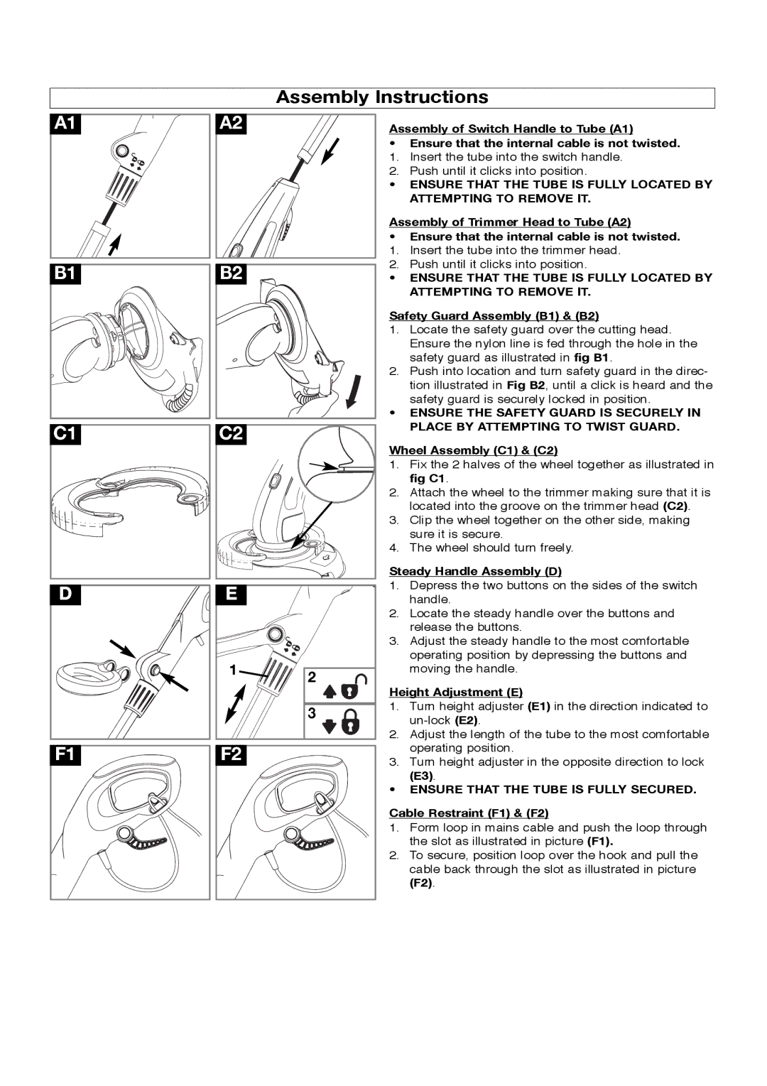
Assembly of Switch Handle to Tube (A1)
•Ensure that the internal cable is not twisted.
1.Insert the tube into the switch handle.
2.Push until it clicks into position.
•ENSURE THAT THE TUBE IS FULLY LOCATED BY ATTEMPTING TO REMOVE IT.
Assembly of Trimmer Head to Tube (A2)
•Ensure that the internal cable is not twisted.
1.Insert the tube into the trimmer head.
2.Push until it clicks into position.
•ENSURE THAT THE TUBE IS FULLY LOCATED BY ATTEMPTING TO REMOVE IT.
Safety Guard Assembly (B1) & (B2)
1.Locate the safety guard over the cutting head.
Ensure the nylon line is fed through the hole in the safety guard as illustrated in fig B1.
2.Push into location and turn safety guard in the direc- tion illustrated in Fig B2, until a click is heard and the
safety guard is securely locked in position.
•ENSURE THE SAFETY GUARD IS SECURELY IN PLACE BY ATTEMPTING TO TWIST GUARD.
Wheel Assembly (C1) & (C2)
1.Fix the 2 halves of the wheel together as illustrated in fig C1.
2.Attach the wheel to the trimmer making sure that it is located into the groove on the trimmer head (C2).
3.Clip the wheel together on the other side, making sure it is secure.
4.The wheel should turn freely.
Steady Handle Assembly (D)
1.Depress the two buttons on the sides of the switch handle.
2.Locate the steady handle over the buttons and release the buttons.
3.Adjust the steady handle to the most comfortable operating position by depressing the buttons and moving the handle.
Height Adjustment (E)
1.Turn height adjuster (E1) in the direction indicated to
2.Adjust the length of the tube to the most comfortable operating position.
3.Turn height adjuster in the opposite direction to lock
(E3).
•ENSURE THAT THE TUBE IS FULLY SECURED.
Cable Restraint (F1) & (F2)
1.Form loop in mains cable and push the loop through the slot as illustrated in picture (F1).
2.To secure, position loop over the hook and pull the
cable back through the slot as illustrated in picture (F2).