|
| Assembly Instructions cont’ | ||
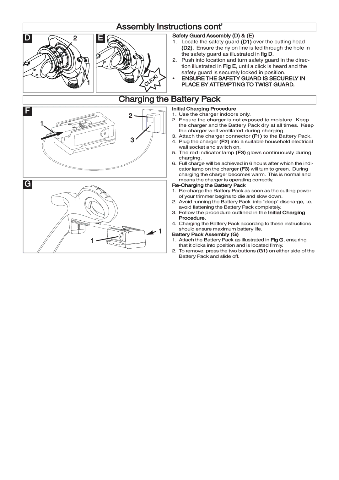
D | 2 | E | Safety Guard Assembly (D) & (E) | |
1. | Locate the safety guard (D1) over the cutting head | |||
|
|
|
| (D2). Ensure the nylon line is fed through the hole in |
|
|
|
| the safety guard as illustrated in fig D. |
|
|
| 2. Push into location and turn safety guard in the direc- | |
|
|
|
| tion illustrated in Fig E, until a click is heard and the |
|
|
|
| safety guard is securely locked in position. |
|
| 1 | • ENSURE THE SAFETY GUARD IS SECURELY IN | |
|
|
| PLACE BY ATTEMPTING TO TWIST GUARD. | |
F |
| Charging the Battery Pack | ||
| 2 | Initial Charging Procedure | ||
| 1. Use the charger indoors only. | |||
| 1 | 2. | Ensure the charger is not exposed to moisture. Keep | |
|
|
| the charger and the Battery Pack dry at all times. Keep | |
|
|
| 3. | the charger well ventilated during charging. |
|
| 3 | Attach the charger connector (F1) to the Battery Pack. | |
|
| 4. | Plug the charger (F2) into a suitable household electrical | |
|
|
| 5. | wall socket and switch on. |
|
|
| The red indicator lamp (F3) glows continuously during | |
|
|
| 6. | charging. |
|
|
| Full charge will be achieved in 6 hours after which the indi- | |
|
|
|
| cator lamp on the charger (F3) will turn to green. During |
|
|
|
| charging the charger becomes warm. This is normal and |
G |
|
|
| means the charger is operating correctly. |
|
|
| ||
|
|
| 1. | |
|
|
| 2. | of your trimmer begins to die and slow down. |
|
|
| Avoid running the Battery Pack into "deep" discharge, i.e. | |
|
|
| 3. | avoid flattening the Battery Pack completely. |
|
|
| Follow the procedure outlined in the Initial Charging | |
|
|
|
| Procedure. |
|
|
| 4. Charging the Battery Pack according to these instructions | |
|
| 1 |
| should ensure maximum battery life. |
|
| Battery Pack Assembly (G) | ||
|
| 1 | 1. | Attach the Battery Pack as illustrated in Fig G, ensuring |
|
| 2. | that it clicks into position and is located firmly. | |
|
|
| To remove, press the two buttons (G1) on either side of the | |
|
|
|
| Battery Pack and slide off. |