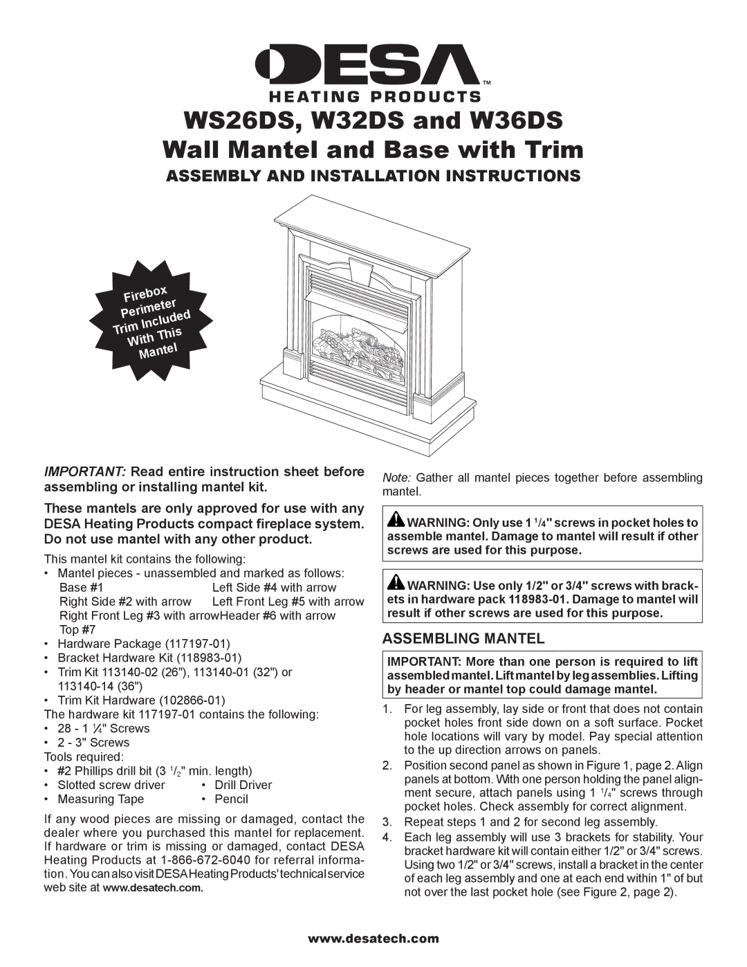
W32DS, WS26DS, W36DS specifications
The FMI WS26DS, W32DS, and W36DS are part of the FMI (Fireplace Manufacturing Inc.) range of gas fireplaces, designed to enhance comfort and aesthetic appeal in residential spaces. Each model brings innovative features and advanced technologies that cater to various consumer needs and preferences.Starting with the WS26DS, this model is compact yet powerful, ideal for smaller living spaces. It offers a contemporary design that can seamlessly fit into modern interiors. One of its standout features is the dual burner system, which allows for adjustable flame heights, enabling users to customize the warmth and ambiance. The WS26DS is also equipped with a glass front that provides an unobstructed view of the flames, creating a cozy atmosphere in any room. The incorporation of a modulating thermostat ensures energy efficiency, maintaining desired temperatures without excessive fuel consumption.
Moving to the W32DS, this mid-sized model offers a larger viewing area while maintaining the sleek design that FMI is known for. The W32DS is designed with a multi-venting system, allowing for versatile installation options, including direct venting through walls or roofs. This feature is particularly beneficial for homeowners looking to install a fireplace in spaces where traditional chimney systems are impractical. The adjustable flame height and remote control functionality enhance user convenience, allowing for effortless operation from a distance. With an emphasis on performance, the W32DS also features heat exchanger technology, maximizing warmth while minimizing heat loss.
Lastly, the W36DS represents the largest offering among these models, catering to those who desire a significant visual impact alongside heating efficiency. Its expansive viewing area is complemented by realistic ember beds and lifelike flames, creating a striking centerpiece in any room. The W36DS is equipped with advanced safety features, including an automatic shut-off system and child safety lock, ensuring peace of mind for families. The unit's impressive BTU output makes it suitable for larger spaces, providing reliable heat even in colder climates. Furthermore, the incorporation of a programmable thermostat allows users to set specific heating schedules, optimizing energy use throughout the day.
In summary, the FMI WS26DS, W32DS, and W36DS models stand out for their innovative design and user-friendly features. With options for various space requirements, these fireplaces not only enhance the aesthetic appeal of homes but also provide efficient heating solutions tailored to modern living. Whether preferring a compact unit or a larger installation, FMI's range ensures that there's a perfect match for every homeowner's needs.