FortiGate HA between two | Base backplane communications and HA between |
FortiGate HA between two FortiGate-5020 chassis
The
The following diagram shows an example of how to connect four FortiGate- 5001SX units installed in two
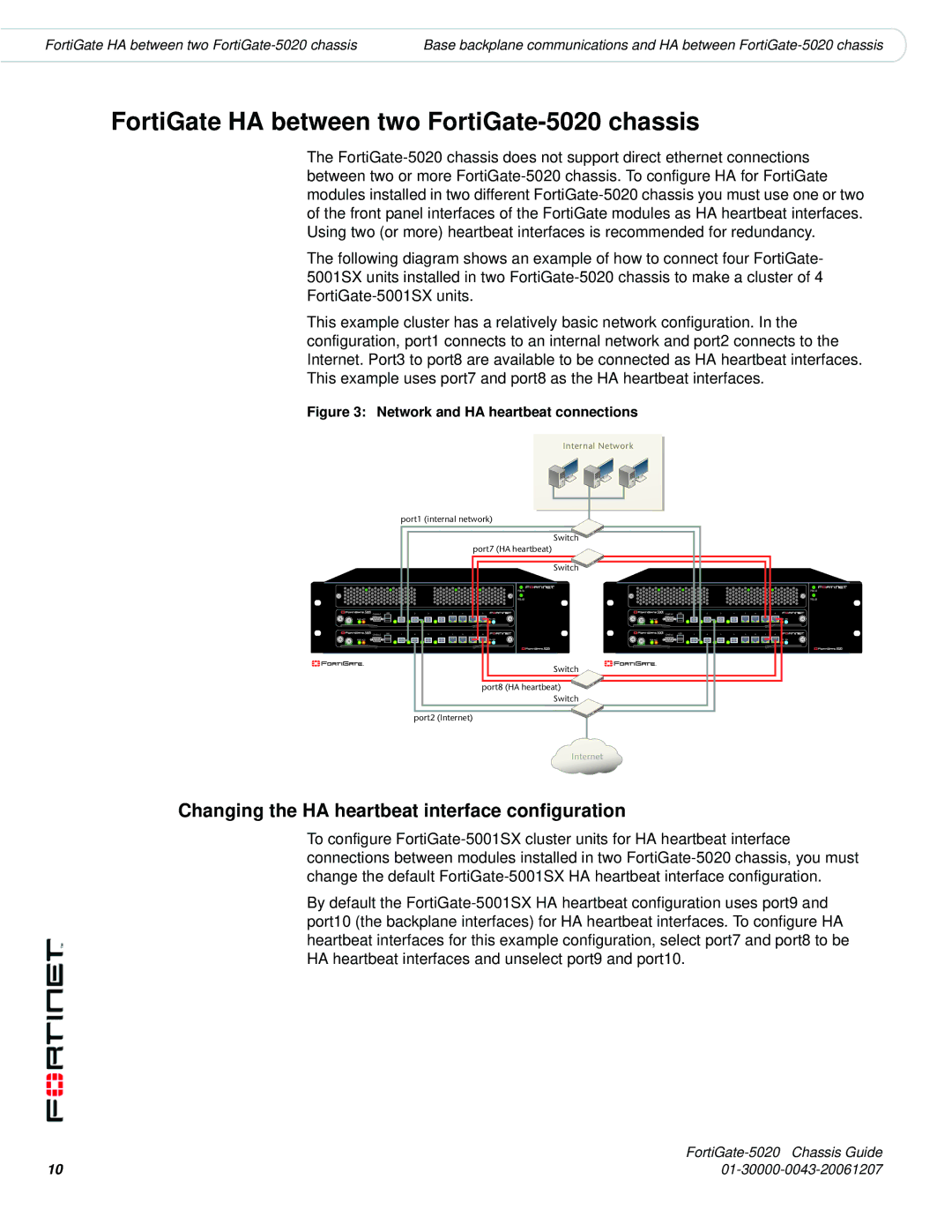
This example cluster has a relatively basic network configuration. In the configuration, port1 connects to an internal network and port2 connects to the Internet. Port3 to port8 are available to be connected as HA heartbeat interfaces. This example uses port7 and port8 as the HA heartbeat interfaces.
Figure 3: Network and HA heartbeat connections
Internal Network
|
| port1 (internal network) |
|
|
|
|
|
|
|
|
|
| |||||||
|
|
|
|
|
|
|
|
|
| Switch |
|
|
|
|
|
|
|
|
|
|
|
|
|
|
|
|
| port7 (HA heartbeat) |
|
|
|
|
|
|
|
|
|
| |
|
|
|
|
|
|
|
|
|
| Switch |
|
|
|
|
|
|
|
|
|
|
|
|
|
|
|
|
|
| PSU A |
|
|
|
|
|
|
|
|
| PSU A |
|
|
|
|
|
|
|
|
| PSU B |
|
|
|
|
|
|
|
|
| PSU B |
CONSOLE | USB | 1 | 2 | 3 | 4 | 5 | 6 | 7 | 8 | CONSOLE | USB | 1 | 2 | 3 | 4 | 5 | 6 | 7 | 8 |
PWR ACC |
|
|
|
|
|
|
|
| STA IPM | PWR ACC |
|
|
|
|
|
|
|
| STA IPM |
CONSOLE | USB | 1 | 2 | 3 | 4 | 5 | 6 | 7 | 8 | CONSOLE | USB | 1 | 2 | 3 | 4 | 5 | 6 | 7 | 8 |
PWR ACC |
|
|
|
|
|
|
|
| STA IPM | PWR ACC |
|
|
|
|
|
|
|
| STA IPM |
Switch
port8 (HA heartbeat) ![]()
![]() Switch
Switch
port2 (Internet)
Internet
Changing the HA heartbeat interface configuration
To configure
By default the
| |
10 |