3.F60 and F85 Technical Data and Operating Instructions

3.1 Technical Data

Model

F60

F85

Output – kg/24hr

60

83

Bin storage capacity – kg

27

27

Cubes per cycle

48

48

Cubes kg per cycle

0.84

0.84

Cycle time – minutes

19.0

15.5

Amps start/run

19/4.1

26/5.5

Watts consumption (30°C Ambient Temp)

630

780

Water consumption (Water Temp at 15°C Air Temp 21°C)

12.0

16.0

Refrigerant

R134A

R134A

Refrigerant charge grams

450 grms

540 grms

Evaporator Temp with Gas Pressure at 10.5 Bar ( Ambient Temp 21°C)

-10°C

-26°C

Evaporator Temp with Gas Pressure at 7.5 Bar ( Ambient Temp 21°C)

-6°C

-25°C

Evaporator Temp with Gas Pressure at 13 Bar ( Ambient Temp 32°C)

-10°C

-28°C

Evaporator Temp with Gas Pressure at 8 Bar ( Ambient Temp 32°C)

-7°C

-24°C

Heat Emission, watts

1100

1400

Noise Level dBA at 2 meters

60

63

3.2Start Up

After having correctly installed the ice machine and completed the plumbing and electrical connections, perform the following “Start-up” procedure.

A.Switch on the power to the machine. The unit starts its first freezing cycle with the following components in operation:

COMPRESSOR WATER PUMP

FAN MOTOR. (The condenser fan is controlled by a thermostat, which is factory set).

B.Check through the ice discharge opening that the spray plate is correctly seated and that the water jets uniformly reach the interior of the inverted cup molds; also make sure that the plastic curtain is hanging freely and that water is not spilling through it excessively.

C.The ice making process takes place thereby, the water is sprayed into the molds which gets gradually refrigerated by the heat exchanged with the refrigerant flowing into the evaporator serpentine.

D.When the evaporator temperature reaches a pre-set value (approximately -15°C) the evaporator thermostat changes its contacts and starts the time clock, when the first timed portion has elapsed the freezing cycle ends and the second timed portion starts the defrost/harvest cycle. Freezing time will range between 20 and 22 minutes (depending on model, see table) in a 21°C ambient. Longer time for temperature above, shorter when below.

Average complete cycle range is about 23 to 25 minutes (depending on model, see table above)

E.Check, during the first defrost/harvest cycle, that the incoming water flows correctly into the sump reservoir in order to re-fill it and the surplus overflows down the overflow drain tube.

During this cycle the components energised are:

COMPRESSOR.

HOT GAS SOLENOID.

WATER INLET SOLENOID VALVE. TIMER MOTOR

FAN MOTOR (if ambient temperature exceeds 30°C).

Note. During the defrost cycle, the water inlet solenoid valve is energised. The water flows through the valve to the back side of the evaporator platen and then down to fill up the icemaker sump tank for the next freezing cycle.

C.Check the texture of the ice cubes just released. The correct size has a small depression (about 5-6mm) in their crown. If not, wait for the second defrost/harvest cycle before making any adjustments.

3.3Adjustments

G.

If after the second harvest the cubes are not correct adjustment to the cube size


thermostat may be necessary.


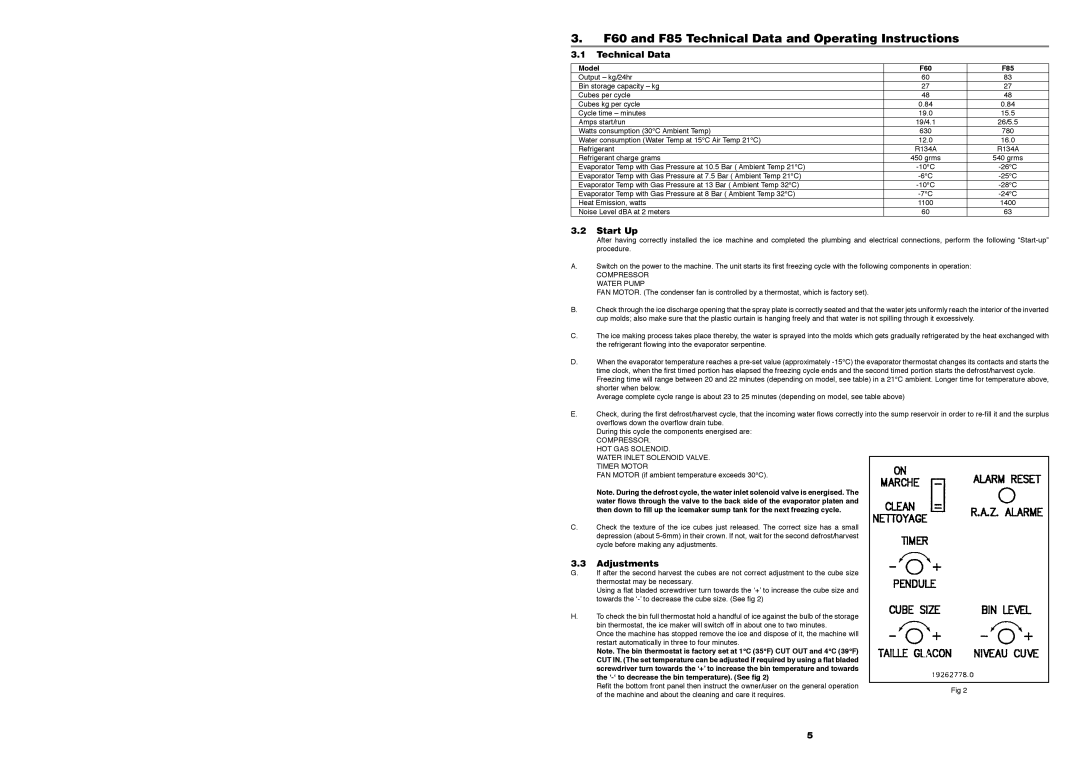
Using a flat bladed screwdriver turn towards the ‘+’ to increase the cube size and


towards the ‘-’ to decrease the cube size. (See fig 2)


H.

To check the bin full thermostat hold a handful of ice against the bulb of the storage


bin thermostat, the ice maker will switch off in about one to two minutes.


Once the machine has stopped remove the ice and dispose of it, the machine will


restart automatically in three to four minutes.


Note. The bin thermostat is factory set at 1°C (35°F) CUT OUT and 4°C (39°F)


CUT IN. (The set temperature can be adjusted if required by using a flat bladed


screwdriver turn towards the ‘+’ to increase the bin temperature and towards


the ‘-‘ to decrease the bin temperature). (See fig 2)


Refit the bottom front panel then instruct the owner/user on the general operation

Fig 2


of the machine and about the cleaning and care it requires.


5

Page 6
Image 6
Foster FCI40, F20, F40, FCI30, FCI85, FCI60, FCI20 F60 and F85 Technical Data and Operating Instructions, Model F60 F85

FCI60, FCI30, FCI20, FCI40, FCI85 specifications

Foster F85, F20, F40, and F60 represent a remarkable lineup of industrial and commercial engines, celebrated for their reliability, efficiency, and advanced technology. These models cater to various applications, striking a balance between performance and economy.

The Foster F85 is designed for smaller machinery and equipment, perfect for light-duty tasks. It features a compact design that allows for easy installation in tight spaces. With a robust power output and energy-efficient operation, the F85 engine is coupled with advanced fuel injection technology that enhances performance and reduces emissions. Its low-maintenance requirements make it a favorite among operators looking for dependable machinery without extensive upkeep.

The Foster F20 escalates the performance, making it suitable for medium-duty applications. It boasts a higher torque output, allowing it to handle more demanding tasks while maintaining excellent fuel efficiency. The F20 integrates cutting-edge electronic control systems that optimize engine performance in real time. This model also features noise reduction technology, contributing to quieter operation in urban or sensitive environments.

Progressing to the Foster F40, this engine shines in heavy-duty applications, offering significant power and efficiency. With a robust design, the F40 is capable of withstanding harsh working conditions without compromising on performance. It features advanced thermal management systems that ensure optimal operating temperatures, enhancing engine lifespan and reliability. Moreover, the F40 incorporates modular components, promoting ease of repair and maintenance.

Lastly, the Foster F60 is the flagship model in this lineup and stands out for its exceptional power-to-weight ratio. It is engineered with the latest innovations in turbocharging, which provides increased horsepower while maintaining low fuel consumption. The F60 also integrates sophisticated diagnostic tools that help operators monitor performance and anticipate maintenance needs, thus minimizing downtime.

Across this range, Foster engines emphasize sustainability through reduced emissions and noise output, adhering to strict industry regulations. From the entry-level F85 to the high-performance F60, each model showcases Foster's commitment to engineering excellence and the evolving needs of industries. Whether for construction, agriculture, or commercial use, the Foster F series represents a wise investment for efficiency and reliability.