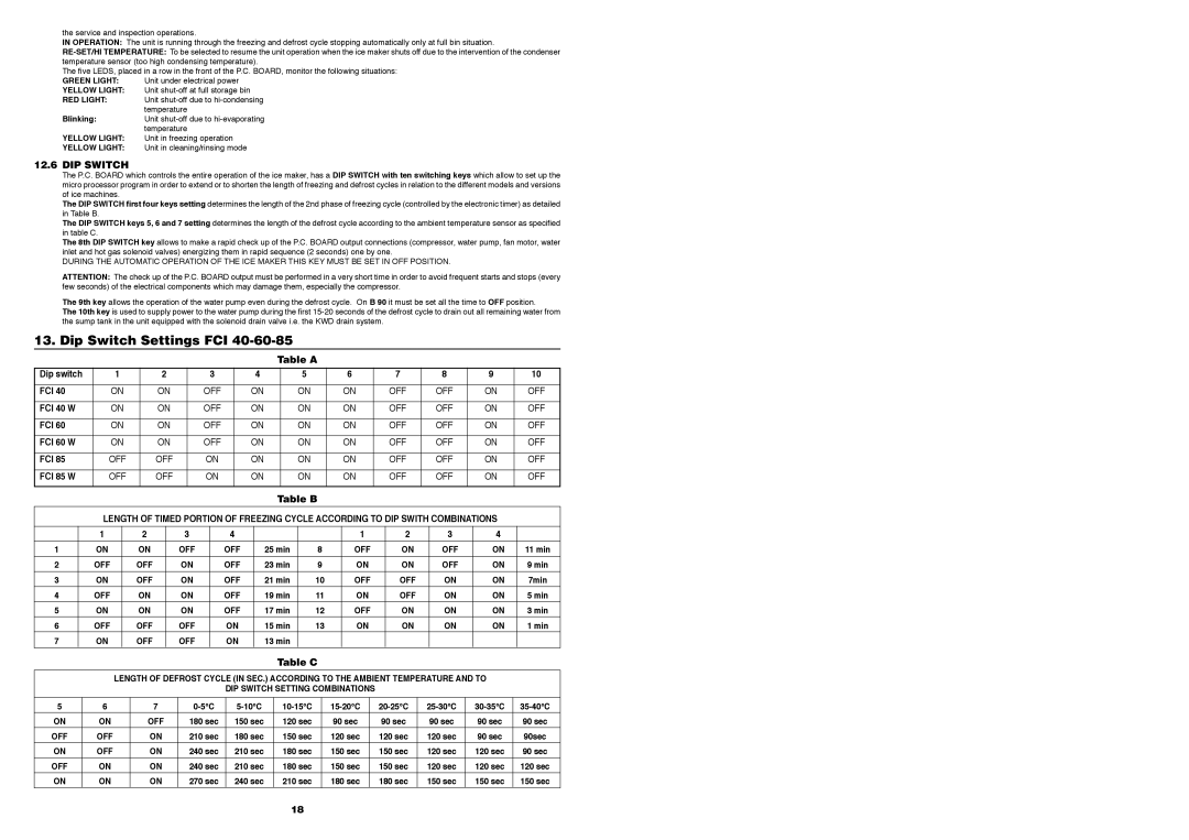
Foster F20, F85, F40 Dip Switch Settings FCI, Table a Dip switch FCI, FCI 40 W, FCI 60 W, FCI 85 W

Models: FCI60 FCI30 FCI20 FCI40 FCI85 F60 F40 F20 F85

1 23
Download 23 pages 51.61 Kb
Page 19
Image 19

the service and inspection operations.

IN OPERATION: The unit is running through the freezing and defrost cycle stopping automatically only at full bin situation.

RE-SET/HI TEMPERATURE: To be selected to resume the unit operation when the ice maker shuts off due to the intervention of the condenser temperature sensor (too high condensing temperature).

The five LEDS, placed in a row in the front of the P.C. BOARD, monitor the following situations:

GREEN LIGHT: Unit under electrical power

YELLOW LIGHT: Unit shut-off at full storage bin

RED LIGHT: Unit shut-off due to hi-condensing temperature

Blinking:Unit shut-off due to hi-evaporating temperature

YELLOW LIGHT: Unit in freezing operation

YELLOW LIGHT: Unit in cleaning/rinsing mode

12.6 DIP SWITCH

The P.C. BOARD which controls the entire operation of the ice maker, has a DIP SWITCH with ten switching keys which allow to set up the micro processor program in order to extend or to shorten the length of freezing and defrost cycles in relation to the different models and versions of ice machines.

The DIP SWITCH first four keys setting determines the length of the 2nd phase of freezing cycle (controlled by the electronic timer) as detailed in Table B.

The DIP SWITCH keys 5, 6 and 7 setting determines the length of the defrost cycle according to the ambient temperature sensor as specified in table C.

The 8th DIP SWITCH key allows to make a rapid check up of the P.C. BOARD output connections (compressor, water pump, fan motor, water inlet and hot gas solenoid valves) energizing them in rapid sequence (2 seconds) one by one.

DURING THE AUTOMATIC OPERATION OF THE ICE MAKER THIS KEY MUST BE SET IN OFF POSITION.

ATTENTION: The check up of the P.C. BOARD output must be performed in a very short time in order to avoid frequent starts and stops (every few seconds) of the electrical components which may damage them, especially the compressor.

The 9th key allows the operation of the water pump even during the defrost cycle. On B 90 it must be set all the time to OFF position.

The 10th key is used to supply power to the water pump during the first 15-20 seconds of the defrost cycle to drain out all remaining water from the sump tank in the unit equipped with the solenoid drain valve i.e. the KWD drain system.

13. Dip Switch Settings FCI 40-60-85

Table A

Dip switch

1

2

3

4

5

6

7

8

9

10


FCI 40

ON

ON

OFF

ON

ON

ON

OFF

OFF

ON

OFF


FCI 40 W

ON

ON

OFF

ON

ON

ON

OFF

OFF

ON

OFF


FCI 60

ON

ON

OFF

ON

ON

ON

OFF

OFF

ON

OFF


FCI 60 W

ON

ON

OFF

ON

ON

ON

OFF

OFF

ON

OFF


FCI 85

OFF

OFF

ON

ON

ON

ON

OFF

OFF

ON

OFF


FCI 85 W

OFF

OFF

ON

ON

ON

ON

OFF

OFF

ON

OFF


Table B

LENGTH OF TIMED PORTION OF FREEZING CYCLE ACCORDING TO DIP SWITH COMBINATIONS


1

2

3

4


1

2

3

4


1

ON

ON

OFF

OFF

25 min

8

OFF

ON

OFF

ON

11 min


2

OFF

OFF

ON

OFF

23 min

9

ON

ON

OFF

ON

9 min


3

ON

OFF

ON

OFF

21 min

10

OFF

OFF

ON

ON

7min


4

OFF

ON

ON

OFF

19 min

11

ON

OFF

ON

ON

5 min

5

ON

ON

ON

OFF

17 min

12

OFF

ON

ON

ON

3 min

6

OFF

OFF

OFF

ON

15 min

13

ON

ON

ON

ON

1 min

7

ON

OFF

OFF

ON

13 min


Table C

LENGTH OF DEFROST CYCLE (IN SEC.) ACCORDING TO THE AMBIENT TEMPERATURE AND TO

DIP SWITCH SETTING COMBINATIONS

5

6

7

0-5°C

5-10°C

10-15°C

15-20°C

20-25°C

25-30°C

30-35°C

35-40°C

ON

ON

OFF

180 sec

150 sec

120 sec

90 sec

90 sec

90 sec

90 sec

90 sec

OFF

OFF

ON

210 sec

180 sec

150 sec

120 sec

120 sec

120 sec

90 sec

90sec


ON

OFF

ON

240 sec

210 sec

180 sec

150 sec

150 sec

120 sec

120 sec

90 sec


OFF

ON

ON

240 sec

210 sec

180 sec

150 sec

150 sec

120 sec

120 sec

120 sec


ON

ON

ON

270 sec

240 sec

210 sec

180 sec

180 sec

150 sec

150 sec

150 sec

18

Page 19
Image 19
Foster F20, F85, F40, F60, FCI30, FCI85, FCI40 Dip Switch Settings FCI, Table a Dip switch FCI, FCI 40 W, FCI 60 W, FCI 85 W

FCI60, FCI30, FCI20, FCI40, FCI85 specifications

Foster F85, F20, F40, and F60 represent a remarkable lineup of industrial and commercial engines, celebrated for their reliability, efficiency, and advanced technology. These models cater to various applications, striking a balance between performance and economy.

The Foster F85 is designed for smaller machinery and equipment, perfect for light-duty tasks. It features a compact design that allows for easy installation in tight spaces. With a robust power output and energy-efficient operation, the F85 engine is coupled with advanced fuel injection technology that enhances performance and reduces emissions. Its low-maintenance requirements make it a favorite among operators looking for dependable machinery without extensive upkeep.

The Foster F20 escalates the performance, making it suitable for medium-duty applications. It boasts a higher torque output, allowing it to handle more demanding tasks while maintaining excellent fuel efficiency. The F20 integrates cutting-edge electronic control systems that optimize engine performance in real time. This model also features noise reduction technology, contributing to quieter operation in urban or sensitive environments.

Progressing to the Foster F40, this engine shines in heavy-duty applications, offering significant power and efficiency. With a robust design, the F40 is capable of withstanding harsh working conditions without compromising on performance. It features advanced thermal management systems that ensure optimal operating temperatures, enhancing engine lifespan and reliability. Moreover, the F40 incorporates modular components, promoting ease of repair and maintenance.

Lastly, the Foster F60 is the flagship model in this lineup and stands out for its exceptional power-to-weight ratio. It is engineered with the latest innovations in turbocharging, which provides increased horsepower while maintaining low fuel consumption. The F60 also integrates sophisticated diagnostic tools that help operators monitor performance and anticipate maintenance needs, thus minimizing downtime.

Across this range, Foster engines emphasize sustainability through reduced emissions and noise output, adhering to strict industry regulations. From the entry-level F85 to the high-performance F60, each model showcases Foster's commitment to engineering excellence and the evolving needs of industries. Whether for construction, agriculture, or commercial use, the Foster F series represents a wise investment for efficiency and reliability.