| ELECTRICAL CONNECTION |
|
• | Remove the cover from the Field Wiring Compartment with a | Green |
| phillips screwdriver. | |
| Ground | |
• | Feed the Power Supply Cable through the electrical knockout. | screw |
| Connect the Power Supply Cable to the range- hood cable. At- |
|
| tach the Power Supply Cable grounding lead to the green screw |
|
| provided. Attach the White lead of the power supply to the |
|
| White lead of the rangehood with a |
|
| tor. Attach the Black lead of the power supply to the Black |
|
| lead of the rangehood with a |
|
• | Replace the cover. |
|
Chimney assembly
Upper exhaust Chimney |
| |
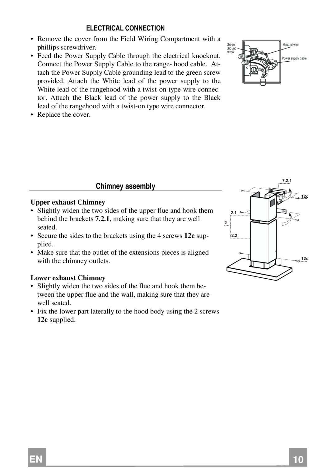
• Slightly widen the two sides of the upper flue and hook them | 2.1 | |
behind the brackets 7.2.1, making sure that they are well | 2 | |
seated. | ||
| ||
• Secure the sides to the brackets using the 4 screws 12c sup- | 2.2 | |
plied. |
| |
• Make sure that the outlet of the extensions pieces is aligned |
| |
with the chimney outlets. |
|
Lower exhaust Chimney
•Slightly widen the two sides of the flue and hook them be- tween the upper flue and the wall, making sure that they are well seated.
•Fix the lower part laterally to the hood body using the 2 screws 12c supplied.
Ground wire
Power supply cable
7.2.1
12c
12c
EN |
| 1 |
| 10 |
