Implementation
3.4 Temperature Sensor Measurement
The temperature sensor measurement is performed based on the methodology of an emulated ADC described in the application note, AN3266 “Getting Started with RS08”.
+
–
MCU BOUNDARY
VDD
RVDD
4k7
![]() 7k5
7k5
C |
|
|
|
|
|
| TEMP SENSOR |
22nF |
|
|
|
|
|
| |
|
|
|
|
|
| 10k | |
|
|
|
|
|
|
| |
|
|
|
|
|
|
|
|
|
|
|
|
|
|
|
|
|
|
|
|
|
|
|
|
|
|
|
|
|
|
|
|
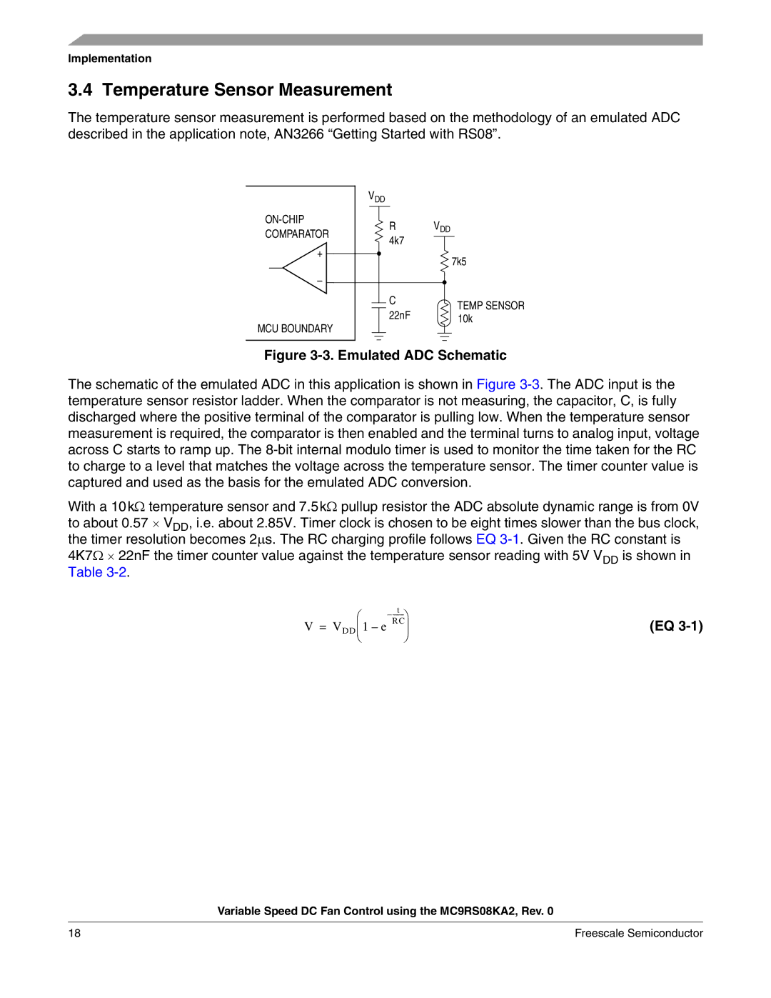
Figure 3-3. Emulated ADC Schematic
The schematic of the emulated ADC in this application is shown in Figure
With a 10kΩ temperature sensor and 7.5kΩ pullup resistor the ADC absolute dynamic range is from 0V to about 0.57 ⋅ VDD, i.e. about 2.85V. Timer clock is chosen to be eight times slower than the bus clock, the timer resolution becomes 2∝s. The RC charging profile follows EQ
⎛ | t |
|
| ||
V = VDD⎜ | 1 – e RC⎟ | (EQ |
⎝ | ⎠ |
|
Variable Speed DC Fan Control using the MC9RS08KA2, Rev. 0
18 | Freescale Semiconductor |