Disassembly
Disassembly
— Before the following disassembly, POWER SWITCH set to OFF and disconnect the power cord.


 Mechanical
 Parts
Parts


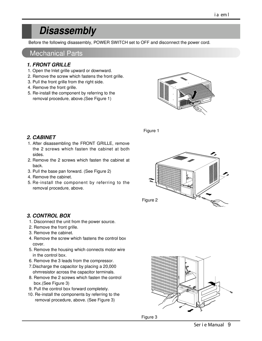
1.FRONT GRILLE
1.Open the lnlet grille upward or downward.
2.Remove the screw which fastens the front grille.
3.Pull the front grille from the right side.
4. Remove the front grille.
5.
Figure 1
2.CABINET
1.After disassembling the FRONT GRILLE, remove the 2 screws which fasten the cabinet at both
sides.
2. Remove the 2 screws which fasten the cabinet at back.
3. Pull the base pan forward. (See Figure 2)
4. Remove the cabinet.
5.
Figure 2
3.CONTROL BOX
1.Disconnect the unit from the power source.
2. Remove the front grille.
3. Remove the cabinet.
4. Remove the screw which fastens the control box cover.
5.Remove the housing which connects motor wire in the control box.
6. Remove the 3 leads from the compressor. 7.Discharge the capacitor by placing a 20,000 ohmresistor across the capacitor terminals.
8. Remove the 2 screws which fasten the control box.(See Figure 3)
9. Pull the control box forward completely.
10.
Figure 3
Service Manual 9