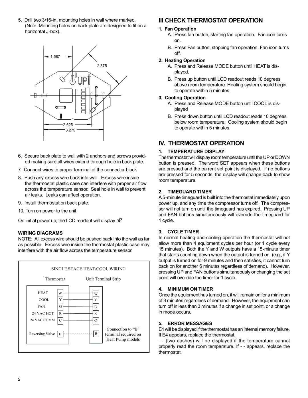
5.Drill two 3/16-in. mounting holes in wall where marked. (Note: Mounting holes on back plate are designed to fit on a horizontal J-box).

1.587

2.375

2.625

3.275

III CHECK THERMOSTAT OPERATION

1.Fan Operation

A.Press fan button, starting fan operation. Fan icon turns on.

B.Press Fan button, stopping fan operation. Fan icon turns off.

2.Heating Operation

A.Press and Release MODE button until HEAT is dis- played.

B.Press up button until LCD readout reads 10 degrees above room temperature. Heating system should begin to operate within 5 minutes.

3.Cooling Operation

A.Press and Release MODE button until COOL is dis- played

B.Press down button until LCD readout reads 10 degrees below room temperature. Cooling system should begin to operate within 5 minutes.

6.Secure back plate to wall with 2 anchors and screws provid- ed making sure all wires extend through hole in back plate.

7.Connect wires to proper terminal of the connector block

8.Push any excess wire back into wall. Excess wire inside the thermostat plastic case can interfere with proper air flow across the temperature sensor. Seal hole in wall to prevent air leaks. Leaks can affect operation.

9.Install thermostat on back plate.

10.Turn on power to the unit.

On initial power up, the LCD readout will display oP.

WIRING DIAGRAMS

NOTE: All excess wire should be pushed back into the wall as far as possible. Excess wire inside the thermostat plastic case may interfere with the air flow across the temperature sensor.

SINGLE STAGE HEAT/COOL WIRING

Thermostat

Unit Terminal Strip

IV. THERMOSTAT OPERATION

1.TEMPERATURE DISPLAY

The thermostat will display room temperature until the UP or DOWN button is pressed. The word SET appears when these buttons are pressed and the current set point is displayed. If no buttons are pressed for 5 seconds, the display will change back to show room temperature.

2.TIMEGUARD TIMER

A 5-minute timeguard is built into the thermostat immediately upon power up, and any time the compressor turns off. The compres- sor will not turn on until the timeguard has expired. Pressing UP and FAN buttons simultaneously will override the timeguard for 1 cycle.

3.CYCLE TIMER

In normal heating and cooling operation the thermostat will not allow more than 4 equipment cycles per hour (or 1 cycle every 15 minutes). Both the Y and W outputs have a 15-minute timer that starts counting down when the output is turned on, (e.g., if Y output is turned on for 9 minutes and then satisfies, it cannot turn back on for another 6 minutes regardless of demand). However, pressing UP and FAN buttons simultaneously or changing the set point will override the timer for 1 cycle.

4.MINIMUM ON TIMER

HEAT

W

W

COOL

Y

Y

FAN

G

G

24 VAC HOT

R

R

24 VAC COMM

C

C

Reversing Valve

B

B

Connection to “B” terminal required on Heat Pump models

Once the equipment has turned on, it will remain on for a minimum of 3 minutes regardless of demand. However, the equipment can turn off in less than 3 minutes if a change in set point, or a change in mode occurs.

5.ERROR MESSAGES

E4 will be displayed if the thermostat has an internal memory failure. If E4 appears, replace the thermostat.

-- (two dashes) will be displayed if the temperature cannot properly read the room temperature. If - - appears, replace the thermostat.

2

Page 2
Image 2
Friedrich RT2 installation instructions III Check Thermostat Operation, IV. Thermostat Operation

RT2 specifications

The Friedrich RT2 is a sophisticated piece of robotic technology that marks a significant leap in automation and efficiency in various industrial applications. Designed with versatility in mind, the RT2 effectively combines cutting-edge features and innovative technologies, ensuring optimal performance in diverse environments.

One of the main features of the RT2 is its advanced mobility system. The robot is equipped with omnidirectional wheels that allow for seamless movement in any direction. This capability is crucial for navigating confined spaces and improving overall operational efficiency. Additionally, the RT2 is designed with a lightweight yet durable chassis, enabling it to handle a variety of payloads without sacrificing speed or agility.

In terms of technology, the Friedrich RT2 incorporates state-of-the-art sensors, including LIDAR and vision systems, that enhance its spatial awareness and obstacle detection. These sensors allow the robot to create detailed maps of its surroundings, facilitating precise navigation and reducing the risk of collisions. The RT2’s real-time data processing capabilities enable it to adapt to changing environments dynamically, which is essential for industries that require high flexibility.

Another noteworthy characteristic of the Friedrich RT2 is its modular design. This feature allows users to customize the robot by adding or replacing components based on specific operational needs. Whether it’s a different tool for material handling or specialized sensors for quality control, the RT2 can be tailored to fit a wide array of tasks.

The RT2 also showcases impressive connectivity options. With support for various communication protocols, including Wi-Fi, Bluetooth, and industrial Ethernet, the robot can seamlessly integrate into smart factories and IoT ecosystems. This connectivity capability enables streamlined data exchange and remote monitoring, empowering operators to optimize processes and improve decision-making.

Furthermore, the Friedrich RT2 prioritizes user-friendly operation. Its intuitive interface and comprehensive software platform simplify programming and task assignment, making it accessible even for those without extensive technical backgrounds.

In summary, the Friedrich RT2 embodies a new era of industrial automation with its cutting-edge mobility, advanced sensing technologies, modular design, robust connectivity options, and user-centric interface. As industries increasingly turn to automated solutions, the RT2 stands out as a versatile and reliable choice for enhancing operational efficiency and productivity.