GAS CONNECTION
1.Remove the shipping cap from gas pipe at the rear of the dryer.
NOTE: DO NOT connect the dryer to L.P. gas service without converting the gas valve. An L.P. conversion kit must be installed by a qualified gas technician.
2.Connect a 1/2 inch (1.27 cm) I.D.
3.Open the shutoff valve in the gas supply line to allow gas to flow through pipe.
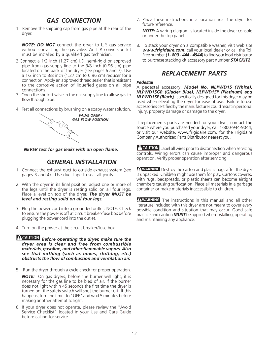
4.Test all connections by brushing on a soapy water solution.
VALVE OPEN /
GAS FLOW POSITION
7.Place these instructions in a location near the dryer for future reference.
NOTE: A wiring diagram is located inside the dryer console or under the top panel.
8.To stack your dryer on a compatible washer, visit web site www.frigidaire.com, call your local dealer or call the Toll Free number (1- 800 - 444 - 4944) to find your local distributor to purchase stacking kit accessory part number STACKIT2.
REPLACEMENT PARTS
Pedestal
A pedestal accessory, Model No. NLPWD15 (White),
NLPWD15GB (Glacier Blue), NLPWD15P (Platinum) and NLPWD15E (Black), specifically designed for this dryer may be used when elevating the dryer for ease of use. Failure to use accessories certified by the manufacturer could result in personal injury, property damage or damage to the dryer.
If replacements parts are needed for your dryer, contact the source where you purchased your dryer, call
NEVER test for gas leaks with an open flame.
GENERAL INSTALLATION
1.Connect the exhaust duct to outside exhaust system (see pages 3 and 4). Use duct tape to seal all joints.
2.With the dryer in its final position, adjust one or more of the legs until the dryer is resting solid on all four legs. Place a level on top of the dryer. The dryer MUST be level and resting solid on all four legs.
3.Plug the power cord into a grounded outlet. NOTE: Check to ensure the power is off at circuit breaker/fuse box before plugging the power cord into the outlet.
4.Turn on the power at the circuit breaker/fuse box.
![]()
![]()
![]()
![]()
![]()
![]()
![]() Before operating the dryer, make sure the dryer area is clear and free from combustible materials, gasoline, and other flammable vapors. Also see that nothing (such as boxes, clothing, etc.) obstructs the flow of combustion and ventilation air.
Before operating the dryer, make sure the dryer area is clear and free from combustible materials, gasoline, and other flammable vapors. Also see that nothing (such as boxes, clothing, etc.) obstructs the flow of combustion and ventilation air.
5. Run the dryer through a cycle check for proper operation.
NOTE: On gas dryers, before the burner will light, it is necessary for the gas line to be bled of air. If the burner does not light within 45 seconds the first time the dryer is turned on, the safety switch will shut the burner off. If this happens, turn the timer to "OFF" and wait 5 minutes before making another attempt to light.
6.If your dryer does not operate, please review the "Avoid Service Checklist" located in your Use and Care Guide before calling for service.
![]()
![]()
![]()
![]()
![]()
![]()
![]() Label all wires prior to disconnection when servicing controls. Wiring errors can cause improper and dangerous operation. Verify proper operation after servicing.
Label all wires prior to disconnection when servicing controls. Wiring errors can cause improper and dangerous operation. Verify proper operation after servicing.
![]()
![]()
![]()
![]()
![]()
![]()
![]() Destroy the carton and plastic bags after the dryer is unpacked. Children might use them for play. Cartons covered with rugs, bedspreads, or plastic sheets can become airtight chambers causing suffocation. Place all materials in a garbage container or make materials inaccessible to children.
Destroy the carton and plastic bags after the dryer is unpacked. Children might use them for play. Cartons covered with rugs, bedspreads, or plastic sheets can become airtight chambers causing suffocation. Place all materials in a garbage container or make materials inaccessible to children.
![]()
![]()
![]()
![]()
![]()
![]()
![]() The instructions in this manual and all other literature included with this dryer are not meant to cover every possible condition and situation that may occur. Good safe practice and caution MUST be applied when installing, operating and maintaining any appliance.
The instructions in this manual and all other literature included with this dryer are not meant to cover every possible condition and situation that may occur. Good safe practice and caution MUST be applied when installing, operating and maintaining any appliance.
12