GAS COOKTOP INSTALLATION INSTRUCTIONS
6. Adjustments
A. Top Pilots Adjustment (Some models)
1.Remove valve knobs, top grates and burner pans.
2.Lift top and prop up with support rod located in the burner box.
3.Follow pilot tubes to their source on manifold pipe and locate filter/pilot adjusting assembly.
4.Light two top pilots with match as shown in figure 13.
Figure 13
5.Adjust pilot flame between 1/8" and ¼" (see figure 14) so that a slight tinge of yellow appears at the top.
Pilot Flame
¼" max. total height
Figure 14
B. Burner Air Shutter Adjustment
The air shutter adjustment for each of the four burners is located at the open end of the venturi tube and sets on the valve hood. Depending on the model, the shutter is either held in place by friction fit or with Phillips head screw.
Air Shutter
Figure 15
If the air shutter needs adjusting, rotate the shutter to allow more or less air to the burner tubes as needed.
For Natural Gas it may be necessary to rotate the air shutter to some point less than half open for normal flame; for LP Gas it may be necessary to rotate the air shutter to a nearly full open setting for a normal flame.
C. Burner Flame Adjustment
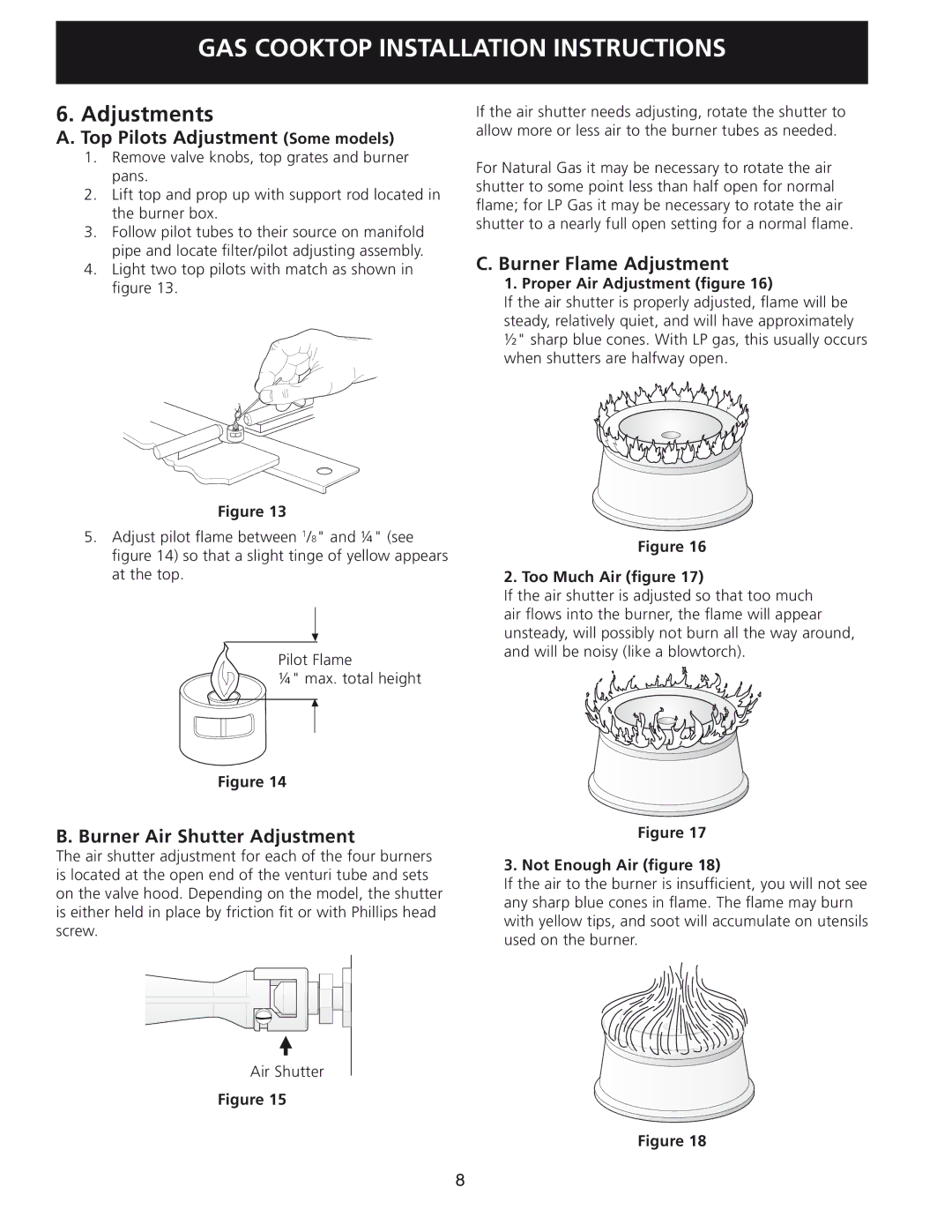
1. Proper Air Adjustment (figure 16)
If the air shutter is properly adjusted, flame will be steady, relatively quiet, and will have approximately ½" sharp blue cones. With LP gas, this usually occurs when shutters are halfway open.
Figure 16
2. Too Much Air (figure 17)
If the air shutter is adjusted so that too much air flows into the burner, the flame will appear unsteady, will possibly not burn all the way around, and will be noisy (like a blowtorch).
Figure 17
3. Not Enough Air (figure 18)
If the air to the burner is insufficient, you will not see any sharp blue cones in flame. The flame may burn with yellow tips, and soot will accumulate on utensils used on the burner.
Figure 18
8