GAS COOKTOP INSTALLATION INSTRUCTIONS
B. 30" Cooktops
Unit Clam Down Information
Once the cooktop is installed in the counter opening, you must clamp the unit down as shown.
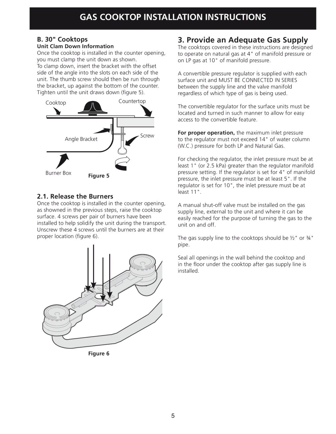
To clamp down, insert the bracket with the offset side of the angle into the slots on each side of the unit. The thumb screw should then be run through the bracket, up against the bottom of the counter. Tighten until the unit draws down (figure 5).
CooktopCountertop
Angle Bracket | Screw |
|
Burner Box | Figure 5 |
|
2.1. Release the Burners
Once the cooktop is installed in the counter opening, as showned in the previous steps, raise the cooktop surface. 4 screws per pair of burners have been installed to help solidify the unit during the transport. Unscrew these 4 screws until the burners are at their proper location (figure 6).
Figure 6
3. Provide an Adequate Gas Supply
The cooktops covered in these instructions are designed to operate on natural gas at 4" of manifold pressure or on LP gas at 10" of manifold pressure.
A convertible pressure regulator is supplied with each surface unit and MUST BE CONNECTED IN SERIES between the supply line and the valve manifold regardless of which type of gas is being used.
The convertible regulator for the surface units must be located and turned in such manner to allow for easy access to the convertible feature.
For proper operation, the maximum inlet pressure to the regulator must not exceed 14" of water column (W.C.) pressure for both LP and Natural Gas.
For checking the regulator, the inlet pressure must be at least 1" (or 2.5 kPa) greater than the regulator manifold pressure setting. If the regulator is set for 4" of manifold pressure, the inlet pressure must be at least 5". If the regulator is set for 10", the inlet pressure must be at least 11".
A manual
The gas supply line to the cooktops should be ½" or ¾" pipe.
Seal all openings in the wall behind the cooktop and in the floor under the cooktop after gas supply line is installed.
5